
Introduction
Viscosity is the most critical rheological property in processes ranging from paint manufacturing to crude oil pipeline transport. For decades, the only reliable way to quantify it was to pull a sample and run it through a laboratory viscometer — a time-consuming ritual that told you what the viscosity was fifteen minutes ago, not what it is right now.
That gap matters more than most engineers realize. In a coating line where viscosity drifts by just 5 cP, you can end up with either sags and runs on the substrate or an orange-peel finish that fails quality inspection. In a polymerization reactor, viscosity increase signals monomer conversion — catch it too late and the batch is ruined.
Inline viscosity measurement changes the entire equation. By mounting a sensor directly in the process line, you get real-time viscosity data every second, enabling closed-loop control that laboratory sampling simply cannot deliver. But is inline always the right choice? And how do you select the right inline viscometer technology for your application?
This guide walks you through everything you need to know — from how inline viscosity sensors work to a detailed head-to-head comparison with laboratory methods, complete with a practical selection framework used by engineers in chemical, coating, food, and energy sectors.
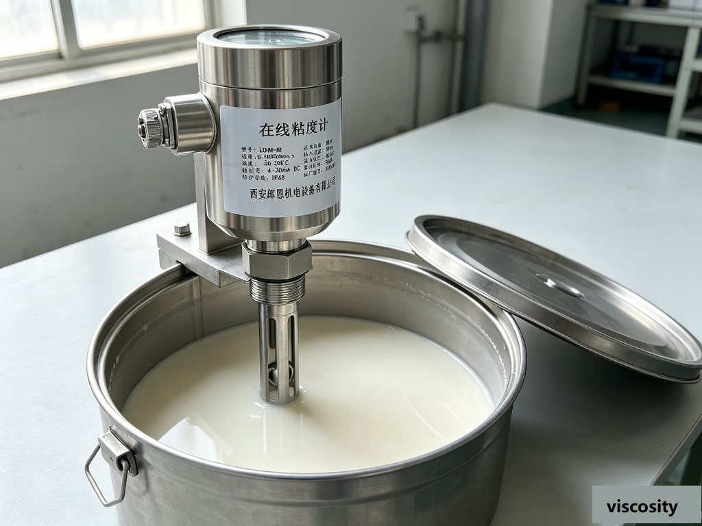
What is Real-Time Viscosity Measurement?
Real-time viscosity measurement means continuously monitoring the viscosity of a process fluid without removing a sample from the stream. The sensor remains in contact with or immersed in the fluid, generating a viscosity signal at intervals of one second or faster.
The viscosity value itself is expressed in centipoise (cP) or milliPascal-seconds (mPa·s), where 1 cP = 1 mPa·s. Water at 20°C has a viscosity of approximately 1.0 cP. Industrial fluids span an enormous range — from light solvents at 0.3 cP to bitumen at over 1,000,000 cP.
Real-time viscosity monitoring is essential in any process where:
- Viscosity changes rapidly due to chemical reactions, temperature fluctuations, or formulation adjustments
- Product quality is directly linked to viscosity targets (coatings, adhesives, polymers)
- Downstream equipment requires stable viscosity inputs to function correctly
- Process efficiency depends on knowing the exact rheological state at any moment
The alternative — laboratory sampling — means working with data that is already historical by the time you receive it. In a 500 m pipeline with a 10 L/min flow rate, the fluid you just sampled left the process vessel 30 minutes ago.
How Inline Viscosity Measurement Works
The Vibrational Viscometer Principle
The most widely deployed technology for inline viscosity measurement is the vibrational viscometer — specifically the vibrating fork or tuning fork design. It works on the principle of damped resonance.
A metallic tuning fork (typically 316L stainless steel or Hastelloy for corrosion resistance) is immersed in the process fluid. The fork is excited at its natural resonant frequency by a piezoelectric actuator. As the fluid’s viscosity increases, the damping effect on the fork’s oscillation increases proportionally, causing:
- A reduction in resonant frequency (Δf)
- A decrease in amplitude (Q factor reduction)
Both parameters are measured continuously. The viscosity is derived from a calibration curve that relates the frequency shift to absolute viscosity. Modern instruments use microprocessor-based algorithms to linearize the relationship and compensate for temperature effects in real time.
Why tuning fork over rotational designs? Rotational viscometers (Brookfield-style) require a rotating spindle immersed in the sample. They are excellent for laboratory use but impractical for inline deployment because the rotating shaft creates a leak path, requires regular bearing replacement, and cannot handle slurries or fibrous media. Vibrational sensors have no moving parts in the process — the entire sensing element is solid-state.
Key Specifications of Modern Inline Viscometers
A properly specified inline viscometer should cover the following performance envelope:
| Parameter | Typical Range |
|---|---|
| Viscosity range | 0.5 – 20,000 cP (extendable to 1,000,000 cP) |
| Accuracy | ±1.0% of full scale (±0.001 cP repeatability, with temperature compensation) |
| Repeatability | ±0.5% of reading (±0.002 cP at reference conditions) |
| Response time | ≤1 second (digital output); ≤100 ms on some models |
| Process temperature | –40°C to +200°C (extensions to 350°C available) |
| Process pressure | Up to 25 bar (standard); up to 100 bar on high-pressure models |
| Process connection | DN25–DN100 flanges; sanitary tri-clamp available |
| Output | 4–20 mA (analog), RS-485 / Modbus RTU (digital) |
| Explosion protection | ATEX Zone 1 / IECEx Ex d available |
| Wetted materials | 316L SS, Hastelloy C-276, Titanium |
Installation Considerations
Proper installation is the single most important factor determining inline viscometer performance. Three rules govern successful deployment:
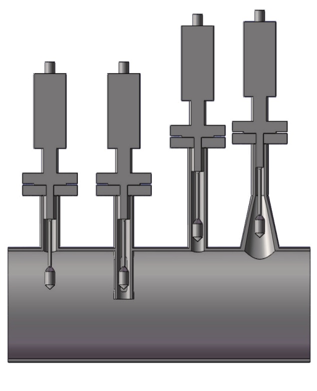
- Maintain a minimum straight run of 5× pipe diameter upstream and 3× downstream to ensure the sensor sees fully developed laminar or turbulent flow without preferential streaming.
- Keep the sensor fully immersed at all times — air pockets cause wild readings. Install horizontally or at 45° for vertical pipes; avoid top-mount installations unless a by-pass loop with level control is used.
- Control temperature at the sensor — viscosity is highly temperature-dependent (most Newtonian fluids change 2–4% per °C). Inline sensors should include built-in Pt100 temperature compensation, or a separate temperature element must feed the same controller.
A common and highly effective configuration is a by-pass loop — a small slipstream diverted from the main process line through the viscometer and returned. This approach allows the sensor to be accessed for maintenance without interrupting production, which is standard practice in chemical plants and refineries with LONNMETER installed bases.
Inline vs Laboratory: Head-to-Head Comparison
Laboratory and inline viscosity measurement answer different questions. The right choice depends on your application, your process dynamics, and what you need to do with the data.
Laboratory Viscosity Measurement
How it works: A sample is extracted from the process, transported to a lab, and measured with a rotational or capillary viscometer. The result is a single-point or flow-curve viscosity reading.
Typical instruments: Brookfield viscometer, Ostwald viscometer, capillary viscometer, rheometer.
Best for: Reference measurements, quality control certification, R&D formulation work, batch release testing.
Limitations:
- Time lag: 15–60 minutes from sample extraction to result
- Cannot drive real-time process control
- Operator-dependent results (sample preparation, temperature equilibration)
- Not continuous — discrete data points only
- Sample alteration: shear history, temperature, and oxidation during sampling can change viscosity
Inline Viscosity Measurement
How it works: Sensor permanently installed in the process line; continuous viscosity signal transmitted to DCS, PLC, or data historian.
Typical instruments: Vibrating fork viscometer, ultrasonic viscometer, microwave viscometer.
Best for: Process monitoring, closed-loop viscosity control, continuous production lines, hazardous environments.
Limitations:
- Higher initial capital cost
- Requires proper installation engineering
- Sensor maintenance (though modern solid-state sensors have MTBF > 50,000 hours)
- Calibration traceable to laboratory standards requires periodic verification
Side-by-Side Comparison
| Criterion | Laboratory Viscosity Measurement | Inline Viscosity Measurement |
|---|---|---|
| Measurement principle | Rotational (spindle/cup), capillary, oscillatory | Vibrational (tuning fork), ultrasonic, microwave |
| Response time | 15–60 min from sample to result | ≤1 second (real-time) |
| Measurement range | 0.1–10,000,000+ cP | 0.5–1,000,000 cP (vibrational) |
| Accuracy | ±1.0% of reading (reference instruments) | ±1.0–2.0% of full scale |
| Data continuity | Discrete data points | Continuous 24/7 stream |
| Temperature control | Precise (controlled bath) | Built-in compensation (RTD Pt100) |
| Sample preparation | Required (filtration, temperature equilibration) | None — in situ |
| Operator dependency | High — technique-dependent | Zero — automated |
| Installation | No process intrusion | Requires process penetration |
| Maintenance | Regular calibration, consumables | Annual verification; MTBF > 50,000 hrs |
| Process interruption | None | Minimal (by-pass loop eliminates it) |
| Hazardous area use | Limited (lab only) | ATEX Zone 1 / IECEx certified models available |
| Typical cost | $2,000–$15,000 per instrument | $5,000–$25,000 per installation |
| Total cost of ownership | Higher (labor, consumables, delays) | Lower over 3–5 years for active processes |
| Ideal use case | Batch QC, certification, R&D | Continuous process control, polymerization, coating |
The Practical Decision Framework
Use laboratory measurement when:
- You need NIST-traceable certification for a specific batch or regulatory submission
- The process runs in discrete batches and viscosity is only checked at release
- You are in the R&D / formulation stage without an established process
- The cost of an inline sensor cannot be justified for low-volume production
Use inline viscosity measurement when:
- Viscosity drifts are causing measurable quality losses or downtime
- You are running a continuous or semi-continuous production line
- Process viscosity directly controls pump speed, spray nozzle pressure, or coating weight
- You need an audit trail of continuous viscosity data for compliance (ISO 9001, FDA 21 CFR Part 11)
- The process involves hazardous materials where removing samples is a safety concern
The hybrid approach is common in practice: inline sensors for real-time control, with periodic laboratory verification of the inline instrument’s accuracy. This provides both the responsiveness of inline measurement and the regulatory traceability of laboratory standards.
Best Practices for Inline Viscosity Monitoring
1. Validate the Viscosity Range Before Purchasing
Inline vibrational viscometers have a defined measurement range. If your process viscosity falls outside the sensor’s calibrated range, you will get either saturating readings or insufficient sensitivity. Confirm the expected range at both minimum and maximum process temperature before specifying a unit.
2. Pair Viscosity with Temperature Measurement
Viscosity and temperature are inseparable. A 20°C rise in a polymer melt at 180°C can halve its viscosity. Every inline viscometer installation should include a calibrated temperature element (Pt100 Class A or better) feeding the same controller as the viscosity signal. The LONNMETER LNV series includes integrated RTD compensation as standard.
3. Use Process Viscosity Control Strategically
Do not set viscosity setpoints based on what the lab measured — use what the inline sensor shows under normal production conditions. Build a baseline during stable production runs, then set control limits at ±2σ from the baseline to allow for normal process variation while catching genuine deviations.
4. Maintain Calibration Traceability
Schedule an annual verification against a laboratory reference viscometer using process fluid at process temperature. Keep the comparison records — they are essential for ISO 9001 audits and demonstrate the EEAT (Experience, Expertise, Authoritativeness, Trustworthiness) that search engines increasingly reward.
5. Choose the Right Process Connection
Flange-mounted sensors (DN25–DN50) are standard for most chemical applications. Sanitary tri-clamp connections are required for food, pharmaceutical, and cosmetic applications. Submarine or insertion-style sensors with hot-tap capability allow installation and removal without shutting down the process on DN100+ lines.
Common Mistakes When Measuring Viscosity Inline
Mistake 1: Ignoring Fluid Type (Newtonian vs Non-Newtonian)
Many engineers specify inline viscometers based on the viscosity range in centipoise without considering whether the fluid is Newtonian or non-Newtonian. Vibrational viscometers measure apparent viscosity at the shear rate imposed by the sensor (typically 100–1,000 s⁻¹). For shear-thinning fluids like paint or polymer solutions, this apparent viscosity will be lower than the zero-shear viscosity measured in a laboratory rheometer.
Solution: Always request a shear rate specification from the instrument manufacturer and compare it against your process shear rate range.
Mistake 2: Installing in a Dead Leg or Low-Flow Zone
Placing a sensor in a stagnant section of pipe means the fluid contacting the sensor is not representative of the bulk stream. Viscosity readings drift as local heating or evaporation changes the fluid properties.
Solution: Ensure flow velocity at the sensor exceeds 0.3 m/s minimum. Use computational fluid dynamics (CFD) simulation for critical applications.
Mistake 3: Neglecting the Effect of Entrapped Gases
Bubbles and entrained gas dramatically increase the damping on a vibrational sensor, producing erroneously high viscosity readings. This is especially problematic in aerated processes or near mixing impellers.
Solution: Install upstream of any aeration point, or use a de-aeration chamber ahead of the sensor.
Mistake 4: Assuming All Viscosity Changes Indicate Process Problems
Fluid property changes (temperature, composition, additives) will show up as viscosity changes in the inline sensor — even when the process itself is behaving correctly. Without temperature compensation and compositional context, operators may chase phantom problems.
Solution: Use multivariate trending — track viscosity, temperature, and pressure together in the DCS. Implement correlation analysis to distinguish genuine process deviations from normal fluid property variations.
Frequently Asked Questions
Q1: Can inline viscometers measure non-Newtonian fluids?
Yes, but with caveats. Inline vibrational viscometers measure apparent viscosity at a defined shear rate. For mildly shear-thinning or shear-thickening fluids, the sensor provides a consistent relative measurement that can be calibrated against laboratory data. For complex rheological behavior, a laboratory rheometer with oscillatory testing is needed for complete characterization.
Q2: How does temperature affect inline viscosity measurements?
Viscosity decreases exponentially with temperature for most liquids — typically 2–4% per °C for Newtonian fluids. Advanced inline viscometers like the LONNMETER LNV series incorporate real-time Pt100 temperature compensation algorithms that adjust the viscosity output to a reference temperature (commonly 25°C or 40°C), giving you stable readings even as process temperature fluctuates.
Q3: What is the maintenance requirement for inline viscometers?
Modern solid-state vibrational viscometers have no moving parts and require minimal maintenance. Annual tasks include a visual inspection of the sensing element (checking for coating, fouling, or erosion), verification of calibration against a reference standard, and inspection of electrical connections and cable integrity. MTBF (Mean Time Between Failures) for LONNMETER inline viscometers exceeds 50,000 operating hours under standard conditions.
Q4: Are inline viscometers suitable for explosive or hazardous environments?
Yes — explosion-proof models with ATEX Zone 1 (Ex d IIC T6) or IECEx certification are available for chemical plants, refineries, and mining operations. The explosion-proof housing ensures that any internal sparking or hot surface cannot ignite surrounding flammable atmosphere. Always specify the correct zone classification for your installation area.
Q5: What is the difference between inline viscosity measurement and online viscosity measurement?
Both terms describe continuous measurement without manual sampling, but “inline” typically means the sensor is inserted directly into the process pipe or vessel, while “online” may refer to a by-pass loop configuration where a portion of the process stream is diverted through a standalone measurement cell. Both configurations are used with LONNMETER sensors, depending on process constraints.
Q6: How do I choose between a vibrational viscometer and a Coriolis mass flow meter with viscosity output?
Coriolis meters provide viscosity as a secondary output derived from the measured density and phase lag. They are excellent choices when you need both density and viscosity simultaneously. Dedicated inline viscometers (vibrational) offer faster response times (≤1 s vs 1–5 s for Coriolis), a wider viscosity range, and typically lower installed cost when viscosity is the primary measurement. If density is equally important, the Coriolis approach may be more cost-effective overall.
Q7: How accurate is inline viscosity measurement compared to laboratory methods?
Modern inline vibrational viscometers achieve ±1.0% of full scale accuracy under controlled temperature conditions, comparable to laboratory rotational viscometers (±0.5–2.0% depending on the instrument). The critical advantage of inline measurement is consistency — the same sensor measures every second without operator variability, so drift over time is the only variable to manage, not day-to-day operator technique differences.
Conclusion
The choice between inline and laboratory viscosity measurement is not a binary one — it is a question of what role viscosity data plays in your process and what decisions it drives.
Inline viscosity measurement is the right choice when:
- Your process runs continuously and viscosity changes need immediate response
- You are controlling quality in real time rather than inspecting it after the fact
- Downstream equipment, coating applications, or filling operations depend on consistent viscosity
- You need 24/7 data logging for compliance, traceability, or process optimization
Laboratory measurement remains indispensable for:
- Regulatory batch certification and NIST-traceable calibration
- R&D and formulation work where rheological characterization is more complex than a single-point measurement
- Low-volume or batch processes where inline instrumentation cost cannot be justified
For most modern continuous and semi-continuous manufacturing processes, inline viscosity monitoring — specifically using a vibrational or tuning fork viscometer — delivers the best combination of accuracy, responsiveness, and total cost of ownership.
At LONNMETER, we have deployed inline viscosity measurement systems across chemical processing, coatings, food production, and mining applications, with installed bases on six continents. Our engineering team provides application-specific sizing and installation support to ensure every sensor delivers its rated performance from day one.
Ready to explore inline viscosity measurement for your process? Contact the LONNMETER engineering team for application sizing, instrument selection support, and a detailed proposal for your specific requirements. You can also request a product datasheet for the L0NN series inline viscometer.
This article is part of the LONNMETER Industrial Measurement Guide series. Related articles: Inline Density Measurement: Technology, Selection & Installation, How to Choose the Right Inline Density Meter, Viscosity Control in Coating Manufacturing.