
Inline Density Measurement: Complete Guide
to Technologies, Selection and Applications
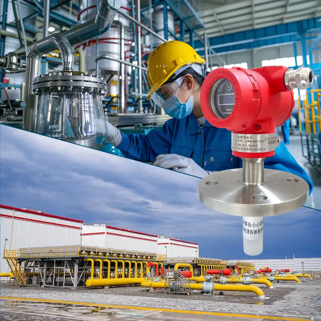
Inline density measurement is the continuous determination of fluid density inside a running process line, without sampling or laboratory analysis. A sensor mounted in the pipe reports density in real time, typically alongside temperature, at intervals fast enough to feed a control loop. From that single physical value a plant can derive solids content in a slurry, acid or caustic concentration, sugar content in °Brix, glycol strength in coolant, and mass-per-volume for custody-relevant streams. This page is the entry point to our complete density resource: how the technologies work, how to choose between them, what degrades accuracy, and which specific process conditions each handles well.
What Is Inline Density Measurement?
Inline density measurement places the measuring element directly in the process stream so the fluid is measured under actual operating temperature and pressure. This distinguishes it from two alternatives: laboratory analysis, where an operator draws a sample and waits hours or days for a result; and offline benchtop instruments, which offer excellent precision but only ever describe the sample as it existed at the moment of drawing.
The practical output is not only density. Because density correlates reproducibly with composition for most binary mixtures, an inline meter becomes a concentration transmitter once the right conversion curve is applied. Density also converts directly into mass when paired with a flow measurement, which is what makes it valuable for material balance, batch endpoint control, and custody transfer.
Three units dominate industrial practice. kg/m³ is the SI form and appears in most datasheets. g/cm³ and g/mL are numerically identical and common in laboratory-adjacent contexts. Specific gravity (SG) is the dimensionless ratio of sample density to water density at a stated reference temperature, usually 4 °C or 20 °C — this is why any SG figure without its reference temperature is ambiguous. Industry-specific scales also exist: °Brix for sucrose solutions, °Baumé and API gravity in petroleum, °Plato in brewing. All are conversions from measured density, not independent measurements.
Throughout this guide, remember one rule that governs everything else: density is temperature-dependent. A meter that reports density without measuring temperature and compensating for it is reporting a moving target. Compensation is not optional.
Why Continuous Density Measurement Matters
From spot checks to process control
Manual sampling is periodic by nature. A shift operator draws a sample every two hours; the laboratory returns a result the next morning. Between those two events the process runs open-loop. If a slurry thickens at 02:00 and the next sample is at 08:00, six hours of off-specification product has already been made, and correction starts six hours late.
An inline meter closes that gap. Update rates of a few seconds mean a density excursion is detected while it is still developing, which changes what the operator can do about it. Instead of rejecting finished product, they adjust dilution, feed rate, or blend ratio and keep the stream in specification.
What the delay actually costs
The economics differ by industry, but four cost centers recur:
• Off-specification product. Material that falls outside tolerance must be reworked, downgraded, or scrapped. In continuous processes the volume affected scales directly with detection time.
• Overcorrection. Operators who lack confidence in their data dilute or blend conservatively, giving away margin on every batch to guarantee the specification is met.
• Laboratory burden. Sampling is manual labor, consumables, and scheduled analysis time, all spent producing data that describes the past.
• Unmeasured variability. Processes cannot be optimized where they are not observed. A stable-looking process may cycle between limits without anyone knowing, because two-hour sampling aliases right past it.
None of these appear as a line item labeled "density measurement." They appear as yield variance, reagent overconsumption, and unexplained quality drift — which is why the return on inline measurement is usually clearer in hindsight than in a business case.
To make it concrete, consider a continuous dilution step where product must leave at a specified density. Sampling every two hours with a four-hour laboratory turnaround means any deviation is known roughly six hours after it began. At a modest line rate, that is several tonnes of material already produced outside tolerance — either reprocessed or sold at reduced value. An inline meter detects the same excursion within seconds, letting the operator correct upstream before off-grade material accumulates. In most such cases the instrument pays for itself through avoided rework alone, and the ongoing benefit is that the process can be run closer to target rather than defensively below it. The exact figure depends entirely on your line rate, product value, and current rework cost, which is why we recommend evaluating it against your own numbers rather than a published average.
How Inline Density Meters Work
Regardless of manufacturer, inline devices derive density by observing how the fluid responds to a physical stimulus. Three families cover essentially all industrial installations.
Vibrating element methods
The most widely deployed approach uses a resonant element immersed in the fluid. The element — commonly a tuning fork, a single rod, or a U-shaped tube — is driven to oscillate at its natural frequency. When fluid surrounds it, the effective vibrating mass increases, and the resonant frequency falls. The relationship between frequency and fluid density follows from the physics of a spring-mass system, so measuring the frequency yields density directly.
Because the element must flex, this method is sensitive to anything that loads it mechanically. High-viscosity fluid damps the oscillation. Deposits that build up on the surface add mass. Entrained gas changes the effective density of the medium contacting the fork. All three are manageable, but each needs to be accounted for at selection time rather than diagnosed after startup.
Coriolis instruments are a closely related case. They also infer density from the resonant frequency of a vibrating tube, but the tube is the full flow conduit rather than an inserted probe, so they measure the whole stream and can additionally derive true mass flow from the Coriolis effect itself. That combination explains both their high accuracy and their cost: you are buying a flowmeter and a densitometer in one instrument.
Acoustic and ultrasonic methods
Ultrasonic instruments propagate a sound pulse through the fluid and measure transit time or sound velocity, both of which vary with density and composition. A key advantage is that some designs are non-invasive — clamp-on transducers measure from outside the pipe wall — which matters where process contamination, pressure, or corrosion makes insertion difficult.
The corresponding weakness is sensitivity to signal path disruption. Gas bubbles scatter ultrasound aggressively, and heavy aeration is genuinely difficult for this method. Sound velocity also responds to temperature and composition independently of density, so these instruments depend heavily on a well-characterized conversion model for the specific fluid.
Differential pressure methods
The oldest continuous method is also the simplest in principle: measure the pressure difference across a fixed vertical column of liquid. Since ΔP = ρgh, knowing the height exactly gives density. It remains relevant for large-diameter lines and tank applications where inserting a probe is impractical and accuracy requirements are moderate.
Accuracy depends almost entirely on how well the column height is known and how stable it stays. Any level uncertainty, any change in fill height, translates directly into density error.
The indispensable role of temperature compensation
Every method above measures something that depends on both density *and* temperature. A tuning fork changes stiffness with temperature. Sound velocity varies with it. Even before that, the fluid's true density changes with temperature as a physical fact.
Practical consequence: temperature compensation is what separates a usable industrial instrument from a thermometer with extra steps. Look for a transmitter that measures process temperature at the sensor, applies the fluid's temperature-density relationship, and reports density referenced to a standard temperature. Ask specifically what conversion model is used for your fluid — generic compensation tables will produce errors on non-aqueous process streams.
Inline Density Measurement Technologies Compared
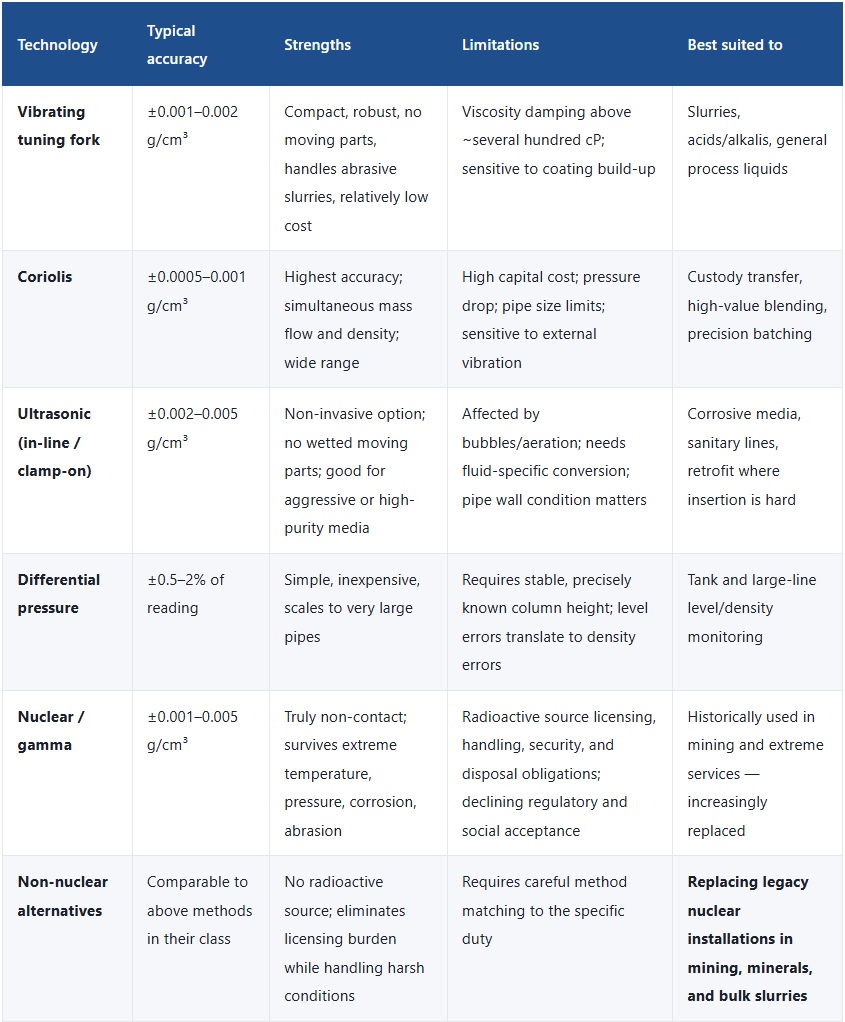
The following comparison reflects typical industrial performance. Exact figures depend on model, fluid, and installation, and manufacturer datasheets should always govern final selection.
Choosing between the three most common paths
In practice most enquiries narrow to three technologies, and the decision usually resolves on one axis.
Vibrating fork versus Coriolis. If you need ±0.0005 g/cm³, simultaneous mass flow, or the measurement supports custody transfer or high-value blending, Coriolis is the defensible choice and the higher capital cost is justified by what it replaces. If process tolerance is looser and the stream is abrasive, viscous at times, or dirty, the mechanical simplicity of a vibrating fork tends to deliver better availability over years of service. When both meet the accuracy requirement, durability in your specific duty should decide it — not the headline specification.
Invasive versus non-invasive. Insertion-type sensors generally deliver better accuracy because they contact the fluid directly. Non-invasive ultrasonic designs win when the process itself resists contact: aggressive chemistry that limits material choices, sanitary duties where cleanability dominates, hygienic certification requirements, or retrofit situations where shutting down to cut into a line is unacceptable. Choose non-invasive when the constraint is real, not as a default preference — you are trading accuracy for installation freedom and should do it consciously.
Keeping or replacing legacy nuclear. Here the deciding factor is almost never measurement. It is whether your organization wants to continue carrying the licensing, access control, trained-personnel, and disposal obligations associated with a sealed source. Modern alternatives cover most of these duties; migration is usually justified on compliance- cost grounds long before the old gauge stops working.
A note on non-nuclear measurement
Many plants operate gamma-based density gauges installed decades ago because nothing else could survive the service. Those instruments were specified when the alternatives were genuinely inferior. They are no longer. Vibrating-fork and ultrasonic designs now cover most mining, mineral processing, and heavy-slurry duties that previously required a radioactive source.
The driver for change is rarely measurement performance — it is the administrative load. A sealed radioactive source carries licensing, periodic leak testing, restricted access, trained personnel, secure storage, and an end-of-life disposal obligation. Removing that burden while retaining measurement capability is usually the stronger business case, even where the instrument itself is still functioning.
How to Select an Inline Density Meter
Selection failures are rarely about picking a "bad" instrument. They come from specifying a good instrument for the wrong duty. Work through these steps in order.
Step 1 — Define what you actually need to know. Density itself is rarely the objective. Solids percentage, acid concentration, °Brix, or blend ratio is. State it that way, because it determines the required resolution. Holding a blend to ±0.5% and holding it to ±0.05% are different instrument classes.
Step 2 — Characterize the fluid honestly. Capture density range, viscosity across the full temperature range, solids content and particle size, abrasiveness, and chemical compatibility with wetted materials. Also state the difficult cases: does the fluid coat surfaces? Does it degas? Does it settle when flow stops? These three questions eliminate candidate technologies faster than any specification sheet.
Step 3 — Establish the installation envelope. Pipe size and material, available straight run, orientation, minimum and maximum process temperature and pressure, ambient conditions, and available power and signal infrastructure. Severe constraints here frequently decide the outcome before accuracy is even discussed.
Step 4 — Set the accuracy target from process tolerance, not from habit. A ±0.0005 g/cm³ instrument costs substantially more than a ±0.002 g/cm³ one. If your process tolerance is 2%, the extra precision buys nothing. Size the specification to the requirement.
Step 5 — Choose the technology that survives the duty. Use the comparison above. Where two technologies meet the accuracy requirement, choose on robustness in your specific service: the mechanical simplicity of a vibrating fork often outruns the theoretical advantage of a more complex device in abrasive slurry.
Step 6 — Plan verification before installation. Decide during selection how you will validate readings after startup. If there is no way to check against a trusted reference, in-service confidence erodes over time and the instrument slowly stops being believed.
Factors That Affect Measurement Accuracy
Even a correctly specified instrument drifts from true value if these are not managed. Each is addressable; the point is knowing they exist.
• Temperature. The largest single source of error when uncompensated. Always verify what compensation model the transmitter applies and whether it matches your fluid.
• Entrained gas and aeration. Bubbles reduce effective measured density and, for ultrasonic methods, scatter the signal. Degassing heads, correct sensor placement, and avoiding high-shear pump discharge all help.
• Coating and fouling. Deposits add mass to a vibrating element and shift its reading downward in apparent density. This is the most common cause of slow, monotonic drift in slurry service.
• Viscosity. Above roughly several hundred centipoise, viscous loading damps a vibrating fork and degrades accuracy. Confirm the specified viscosity limit against your worst case, not your typical case.
• Sedimentation. In slurries that settle at low velocity, the sensor may measure carrier fluid rather than bulk suspension. Maintain minimum line velocity and mount the sensor where solids remain entrained.
• Installation position. Vibrating elements need full immersion and should avoid dead legs, pockets where gas accumulates, and locations where solids can pack around the element.
• External vibration. Coriolis and other resonant devices can pick up pump and structural vibration. Isolation and correct mechanical support resolve this at installation time.
• Calibration drift. All instruments drift. Establish a verification interval from observed process behavior rather than from the datasheet alone.
Common Process Challenges
Most inquiries we receive trace back to one of four recurring problems.
Material inconsistency. Feedstock varies between batches or shipments, and downstream steps absorb the variation. Density confirms whether incoming material meets specification and, more usefully, allows blending to a target rather than accepting whatever arrives.
Limited process visibility. Operators run conservatively because they cannot see inside the line. Continuous measurement converts an inferred state into an observed one and typically lets setpoints move closer to true limits.
Production variation. Same recipe, different result. Unmeasured density shifts explain a large share of this and are otherwise invisible in batch records.
High manual intervention. Every manual adjustment introduces operator-to-operator variation and labor cost. Automating density-dependent adjustments removes both, provided the instrument is trusted.
Density Measurement by Process Condition
Each condition below imposes different demands. Select from the condition, not from the product list.
• Slurry density measurement — solids content in abrasive, settling, often aerated media; the most demanding common duty
• Mining slurry and coal washing — high solids loading, extreme abrasion, historically served by nuclear gauges
• Sulfuric acid density control — strong acid across a wide concentration range where accuracy drives both safety and product value
• Hydrochloric acid concentration — aggressive chemistry requiring compatible wetted materials
• Battery electrolyte production — tight composition control in a fast-growing application
• Food-grade and beverage measurement — hygienic design, cleanability, and sanitary certification requirements
• Very high temperature duties · High pressure lines · Hydrochloric acid to concentration output
Density Measurement by Industry
Concentration Applications Derived from Density
Because density maps to composition for binary mixtures, many concentration measurements are performed with density instruments:
Troubleshooting and Resources
Technology Deep Dives
Benefits of Inline Density Measurement
Continuous real-time monitoring. Density is known now, not later. This is the enabling benefit from which the others follow.
Improved process stability. Closed-loop control on a measured variable holds the process nearer its target and reduces variance in downstream quality metrics.
Reduced manual sampling. Sampling shifts from routine to exception-based verification, cutting both labor and the exposure associated with manual handling of hazardous streams.
Industrial system integration. Modern transmitters output 4–20 mA, Modbus, or digital protocols and integrate directly with PLC and DCS infrastructure, making the measurement available to whatever control logic already governs the process.
Taken together, these benefits compound. Real-time visibility enables control; control reduces variance; reduced variance permits tighter specification and less giveaway; and lower giveaway improves margin without changing the product or the plant. This is why density measurement is usually evaluated too narrowly when it is assessed as an instrument purchase rather than as an operating cost reduction.
Where to Start
If you are new to inline density measurement, the shortest path through this resource is: read how inline measurement works to understand what the instruments measure, use the selection guide to narrow technologies against your actual duty, then review the installation guide before specifying anything — because installation choices made at design time determine accuracy for the life of the instrument.
If you already have an installation and are here to solve a problem rather than specify one, start with the accuracy factors section above and match your observed symptom against the error shapes described there.
Recommended Inline Density Instruments
LONNMETER builds instruments for inline, portable, and ultrasonic duties. Selection should follow from the conditions above; these are representative options.
Browse the full range: Density Meters · All density applications
Frequently Asked Questions
Q: What is the difference between density and specific gravity?
A: Density is mass per unit volume with units, such as kg/m³ or g/cm³. Specific gravity is the dimensionless ratio of a sample's density to water density at a stated reference temperature. Because water density changes with temperature, an SG value is incomplete without stating whether it references 4 °C, 20 °C, or another basis.
Q: How accurate are inline density meters?
A: Typical inline performance runs ±0.001 to ±0.002 g/cm³ for vibrating fork instruments and can reach ±0.0005 g/cm³ for Coriolis devices. Achieved accuracy depends on calibration quality, temperature compensation, and installation. Many reported accuracy problems originate in installation rather than in the instrument.
Q: Can one density meter measure different fluids?
A: Usually yes, provided each fluid has a defined density-concentration relationship loaded into the transmitter and the wetted materials are chemically compatible. Switching between fluids with very different densities or viscosities generally requires recalibration or loading a separate conversion curve.
Q: Why does my density reading drift slowly over time?
A: Progressive drift most often indicates coating build-up on the vibrating element, which adds apparent mass to the element. Secondary causes include sensor aging, changing process temperature beyond the compensation range, or gradual sedimentation around the sensor. Establish a cleaning interval based on observed drift rate.
Q: Are nuclear density meters still worth installing?
A: For almost all new installations, no. Non-nuclear technologies now cover the duties that once required a radioactive source, without the licensing, handling, and disposal obligations. Migration is normally driven by compliance burden rather than measurement failure. See non-nuclear options.
Q: Does viscosity affect density measurement?
A: Yes, particularly for vibrating element designs. Above roughly several hundred centipoise, viscous loading damps the oscillation and degrades accuracy. Always check the specified viscosity limit against your worst operating case rather than your typical case.
Q: Do density meters need temperature compensation?
A: Effectively always. Both the fluid's true density and the sensor's response vary with temperature. A quality transmitter measures temperature at the sensor and applies a compensation model for that specific fluid. Verify which model your transmitter uses — generic water-based tables introduce error on other liquids.
Q: How often should an inline density meter be calibrated?
A: There is no universal interval. Base the schedule on observed drift in your service, then shorten it for abrasive or coating fluids and lengthen it for clean, stable processes. Comparing against a trusted portable or laboratory reference periodically is more informative than any fixed calendar rule. See planned resources on calibration and accuracy factors.
Q: What installation mistakes cause the most problems?
A: Three dominate. Installing where gas can accumulate around the sensor and going partially unwetted; installing with insufficient velocity so solids settle out of suspension; and ignoring the manufacturer's orientation requirement so material packs around the vibrating element. All three are difficult to correct after commissioning but straightforward to avoid during design.
Q: Can density measurement replace composition analysis entirely?
A: It can for simple binary mixtures with a well-established density-to-concentration relationship, including most acid, caustic, sugar, glycol, and alcohol applications. It cannot for multi-component blends where several compositions can yield the same density — no single physical property can resolve those ambiguities. Where composition must be known unambiguously in a complex mixture, density is best used as a fast continuous proxy with periodic laboratory confirmation rather than as a total replacement.
Q: Do I need a separate flow meter too?
A: Only if you need mass flow rather than mass per unit volume. Density multiplied by volumetric flow gives mass flow, so a flow measurement is required whenever you need a mass rate or totalized mass — common in billing, blending by mass, and material balance work. A Coriolis instrument supplies both measurements from one device, which partly explains its cost position.
Q: What should I check first if readings look wrong?
A: Work through four items in order: confirm temperature compensation is active and correct for the fluid; check for entrained gas or aeration; inspect the sensor for coating or deposits; verify the sensor is fully immersed and correctly oriented with no dead leg or solids packing.
Discuss your application: contact LONNMETER for a measurement review of your specific duty.