Coriolis Density Meter: How It Works
A Coriolis density meter measures fluid density from the resonant frequency of a vibrating tube through which the process fluid flows. In practice it is a Coriolis mass flow meter whose electronics also report density: the same vibrating tube that reveals mass flow through the Coriolis-induced phase shift also reveals density through its resonant frequency. Because the resonant frequency of a tube depends on the total mass it carries, the fluid's density shows up directly in the vibration.
This guide explains the physics, the sensor construction, how density is separated from mass flow, the measurement cycle, and where a Coriolis meter is the right — and wrong — choice versus a tuning fork or ultrasonic meter.
What Is a Coriolis Density Meter
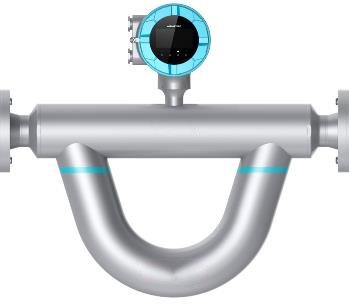
A Coriolis density meter is an inline instrument that determines the density (and simultaneously the mass flow) of a liquid or gas from the behavior of one or more vibrating tubes. The tube is driven
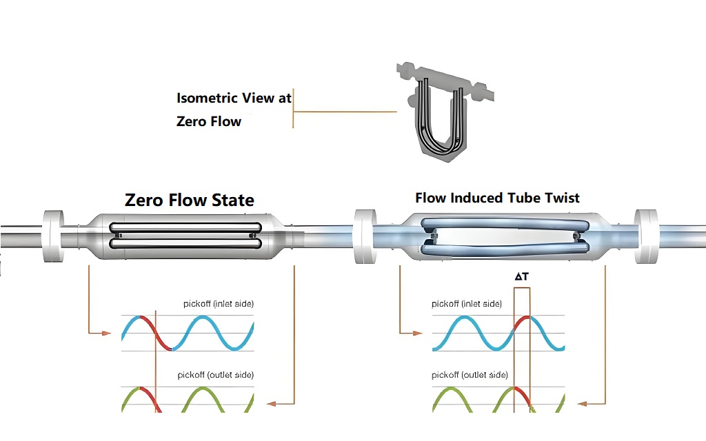
electromagnetically at its mechanical resonance and kept oscillating while fluid passes through. Two things happen at once: the flowing fluid experiences a Coriolis acceleration that twists the tube and creates a phase shift between the inlet and outlet sides (that shift gives mass flow), and the fluid's mass loads the tube and lowers its resonant frequency (that frequency gives density).
Unlike a tuning fork density meter, which is a point sensor that measures density only, a Coriolis meter measures mass flow and density together. Unlike a radiometric gauge, it carries no radioactive source. And unlike an ultrasonic meter, it infers density from the mechanical resonance of a wetted tube rather than from sound speed across a path.
The Physics: Coriolis Force, Phase Shift, and Resonant Frequency
The tube behaves like a vibrating beam. Its drive mode has a natural resonant frequency f_d set by the stiffness k of the tube and its effective vibrating mass m:
The vibrating mass is the tube's own mass plus the mass of fluid trapped inside it. If the tube holds a fixed fluid volume V, then m = m_tube + ρV. Denser fluid adds more mass, lowers f_d, and the relationship is monotonic over the operating range — so the meter converts the measured resonant frequency into density through a factory calibration:
That is the density path. The mass-flow path comes from the Coriolis effect: when fluid flows through the oscillating tube, the inbound and outbound halves experience opposite Coriolis accelerations, twisting the tube. The resulting time delay Δt between the inlet and outlet pickoffs is proportional to mass flow rate ṁ:
So one vibrating tube yields two independent measurements — mass flow from the time delay, density from the resonant frequency — at the same instant.
How Density Is Extracted from the Vibrating Tube
Beginners often conflate the two signals. They are distinct:
The density reading does not require flow. Even at zero flow, the tube still vibrates at its resonant frequency, and that frequency still reflects the fluid's density. This is why a Coriolis meter can serve as a density meter even when the line is stopped — and why its density accuracy often rivals or beats a dedicated density meter.
The instrument resolves the resonant period to very high precision, applies temperature and (where modeled) pressure compensation, and reports density continuously.
Inside the Sensor: Tubes, Drivers, Pickoffs, and Electronics
A typical Coriolis flow-and-density transmitter contains:
The split-tube (balanced) design cancels most reaction forces on the case; straight-tube designs reduce pressure drop but are more sensitive to external vibration.
The Measurement Cycle Step by Step
1. Excitation — the drive coil oscillates the tube at its natural resonant frequency.
2. Pickoff sensing — inlet and outlet pickoffs capture tube motion; the electronics measure both the resonant period and the time delay between them.
3. Temperature read — the RTD reports tube temperature for compensation.
4. Mass-flow computation — firmware converts the time delay into mass flow rate.
5. Density computation — firmware converts the resonant frequency into density via the calibration curve, compensated for temperature (and pressure where applicable).
6. Output — mass flow, density, temperature, and derived values are sent as 4–20 mA, HART, Modbus RTU, Foundation Fieldbus, or EtherNet/IP to the DCS/PLC.
The cycle runs continuously; there is no sampling and no laboratory step.
Mass Flow and Density from One Vibrating Tube
The headline advantage is two measurements from one installation. A plant that needs both mass flow and density — custody transfer, batching, blend control — gets both without a separate density meter and without extra piping penetrations. Where density alone is needed, a Coriolis meter still delivers it, but at a higher installed cost than a dedicated point-density sensor such as a tuning fork.
The trade-off is explicit: you pay for flow measurement you may not use. If you only need density, a tuning fork or ultrasonic meter is leaner and cheaper.
Temperature and Pressure Compensation
Density is temperature-dependent and, for compressible fluids, pressure-dependent. The embedded RTD measures tube temperature every cycle; the meter applies the fluid's thermal expansion and, where modeled, compressibility to report density at reference conditions. For gases and for tight custody-transfer accuracy, pressure compensation matters and must be in the configuration.
Confirm the calibration covers your full operating temperature band — the LONNMETER Coriolis range spans roughly −240 °C to +350 °C depending on model, but a given sensor is specified for a sub-range.
Typical Specifications
Values below are typical for industrial Coriolis flow-and-density meters and reflect the LONNMETER Coriolis specification. Confirm against the actual datasheet and your model before quoting to a customer.
Accuracy: Why Coriolis Density Is Among the Best
Coriolis density accuracy (±0.0005–0.002 g/cm³) sits at the top of the inline field, comparable to a U-tube reference meter and better than a tuning fork (±0.001–0.002 g/cm³) or ultrasonic (±0.001–0.005 g/cm³) for most duties. The reason is the direct mechanical resonance: density is read from the tube's own vibration, not inferred from sound speed through a calibration-heavy path.
For custody transfer and high-value blending, that accuracy — plus the simultaneous mass-flow reading — is what justifies the cost. For general monitoring, a tuning fork or ultrasonic meter is usually enough.
Installation: Orientation, Piping, and Vibration Isolation
Coriolis meters are sensitive to two things the other principles tolerate better:
A Coriolis meter must be fully flooded and free of entrained gas to read correctly; this is a stricter install rule than for a clamp-on ultrasonic.
Outputs and Integration
Coriolis transmitters speak every control-room protocol: 4–20 mA plus HART, Modbus RTU, Foundation Fieldbus, or EtherNet/IP. They carry mass flow, density, temperature, and totalized mass to a DCS/PLC or SCADA, and support alarm limits, Smart Meter Verification, and diagnostics. For custody transfer, use the digital bus to carry full-resolution values rather than the 4–20 mA span.
Where Coriolis Excels — and Where It Doesn't
Coriolis vs Tuning Fork vs Ultrasonic
All three are non-radioactive inline technologies, but they solve different problems: