In the mining and mineral processing industry, slurry density is not just a process parameter — it is the key variable that determines whether your concentrator is making money or burning through it.
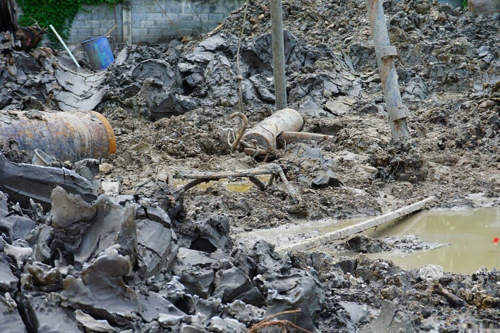
Slurry — a mixture of solid particles suspended in water — flows through every stage of ore processing: grinding, classification, flotation, thickening, and tailings disposal. The density of that slurry (expressed as % solids by weight or specific gravity) directly controls:
- Flotation recovery rates — too dilute and you lose fines; too thick and you lose selectivity
- Grinding circuit efficiency — density affects ball mill throughput more than any other variable
- Thickener performance — the underflow density sets your water recovery rate and downstream pumping costs
- Tailings dam stability — density determines how much water you return to the plant and how much you store in the dam
Despite this, slurry density measurement remains one of the most problematic instrumentations in the typical mineral processing plant. Traditional nuclear gauges are facing increasing regulatory pressure and safety concerns. Manual sampling is inaccurate, slow, and exposes operators to hazardous areas.
This guide covers everything you need to know about slurry density measurement: the available technologies, how to select the right instrument for your application, installation best practices, and a detailed comparison of nuclear versus non-nuclear approaches.
What is Slurry Density and Why Does It Matter?
Slurry density is defined as the mass of solid particles per unit volume of the slurry mixture, expressed either as:
- % Solids by weight (wt%): The ratio of dry solid mass to total slurry mass, multiplied by 100
- Specific gravity (SG): The ratio of slurry density to water density (water = 1.000 at 4°C)
- % Solids by volume (vol%): The ratio of solid volume to total slurry volume
For most mining operations, % solids by weight is the standard reporting unit. Typical ranges vary dramatically by process stage:
| Process Stage | Typical Slurry Density (% Solids by Weight) |
|---|---|
| Ball mill feed | 60–75% |
| Hydrocyclone overflow | 10–35% |
| Flotation feed | 30–45% |
| Flotation concentrate | 50–70% |
| Tailings (thickener feed) | 15–30% |
| Thickener underflow | 45–65% |
| Paste backfill | 65–80% |
The density range that a sensor must cover — and the shear conditions it will encounter — varies more by process stage than in almost any other industry.
Technologies for Slurry Density Measurement
1. Nuclear Density Meters (Radiometric)
Principle: A radioactive source (typically Cesium-137 or Cobalt-60) emits gamma radiation through the pipe. A detector on the opposite side measures the transmitted radiation intensity. The attenuation of gamma radiation is proportional to the density of the medium — the higher the solids concentration, the more radiation is absorbed.
Pros:
- Works in extremely high-density slurries (up to 75–80% solids)
- Proven technology with decades of field data
- Insensitive to flow velocity, turbulence, and bubble content
- Non-intrusive — source and detector mounted externally on the pipe
Cons:
- Radiation safety regulations — licensing, training, periodic inspections, and decommissioning costs
- Regulatory tightening — many jurisdictions are restricting new nuclear gauge installations
- Source replacement — Cs-137 has a 30-year half-life; Co-60 needs replacement every 5–7 years
- Security concerns — theft or misuse of radioactive sources is a serious risk
- High total cost of ownership —licensing, compliance, and disposal costs add up significantly
2. Non-Nuclear Inline Density Meters
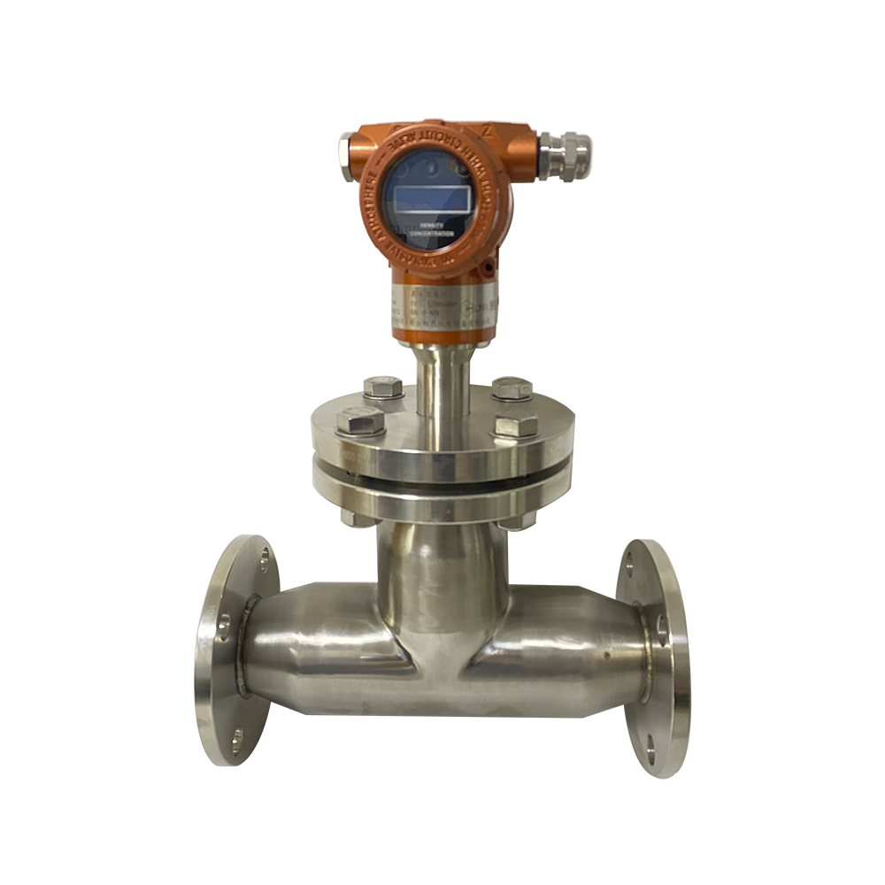
The most widely deployed non-nuclear technology for slurry applications is the ultrasonic density meter, with a secondary role for tuning fork density meters in lower-solids applications.
Ultrasonic Density Meters
Principle: An ultrasonic transducer emits high-frequency pulses (typically 0.5–5 MHz) through the slurry. The speed of sound in the slurry is a function of both the density and the solids concentration. By measuring the time-of-flight difference between upstream and downstream transducers, the instrument calculates the slurry density.
Key advantages for mining:
- No radiation — no licensing, no safety officer requirements, no regulatory compliance burden
- Can be installed in ATEX Zone 1 hazardous areas with proper certification
- Inline installation (sensor in contact with slurry) gives fast response (≤2 seconds)
- Suitable for pipes from DN50 to DN500 — covers the full range of slurry pipelines
- Solid-state sensor with no moving parts, resistant to abrasion from slurries
Typical specifications for mining applications:
- Measurement range: 1.000–2.500 g/cm³ (0–75% solids depending on ore specific gravity)
- Accuracy: ±0.001–0.002 g/cm³
- Response time: ≤2 seconds
- Process temperature: –10°C to +80°C (standard); extended range available
- Process pressure: Up to 25 bar
- Sensor materials: 316L SS (standard), Hastelloy C-276 (corrosive slurries), ceramic wear-resistant options
- Output: 4–20 mA + RS-485 / Modbus RTU; HART available
Tuning Fork Density Meters
Tuning fork density meters work on the damped resonance principle described in our inline density measurement guide. They are best suited for lower-solids applications (typically <15% solids) such as thickener overflow, process water, and chemical addition streams. In high-solids slurry, the vibrating fork can experience coating and fouling that degrades accuracy.
3. Coriolis Mass Flow Meters
Coriolis meters measure density as a secondary output derived from the resonant frequency of the vibrating flow tubes. They offer excellent accuracy (±0.0005 g/cm³ for density) but are susceptible to wear in high-solids slurries and are limited in pipe size (typically DN3–DN150). They are best suited for laboratory-scale or pilot plant slurry measurement.
How to Select the Right Slurry Density Meter
Selecting the correct slurry density measurement technology requires evaluating five key dimensions:
1. Solids Concentration Range
The single most important selection criterion. Match the sensor’s density range to your process:
- < 15% solids: Tuning fork density meter is viable and economical
- 15–50% solids: Ultrasonic inline density meter is the standard choice
- 50–80% solids: Nuclear gauge or specialized high-density ultrasonic sensors
- > 80% solids or paste: Nuclear gauge typically required; alternative technologies still developing
2. Pipe Size
Inline sensors are sized to the process pipe. Most mining slurry lines are DN80–DN300. Ultrasonic sensors handle this range well. Nuclear gauges work on any pipe size but require specific source/detector geometry for each application.
3. Wear and Abrasion
Slurry abra
`siveness is a function of ore mineralogy, particle size distribution, and flow velocity. Silica-rich ores (iron ore, copper sulfide, gold) are extremely abrasive. Choose:
- Hard-faced sensor tips (tungsten carbide coating, ceramic inserts)
- Replaceable sensor inserts for cost-effective maintenance
- By-pass loop installation to allow sensor removal without process shutdown
4. Measurement Accuracy Required
Typical plant control accuracy requirements:
- Flotation circuit: ±0.5–1.0% solids accuracy is sufficient for process control
- Thickener underflow: ±1.0–2.0% solids; water recovery is the key driver
- Paste backfill: ±1.0% solids; consistency is critical for underground placement
- Concentrator grade control: ±0.1–0.2% solids may be needed in some operations
5. Regulatory and Safety Environment
If your operation is in a region with strict radiation regulations (EU, Australia, parts of North America), non-nuclear options should be the default. The total cost of nuclear gauge ownership — licensing, training, inspections, source management, and eventual decommissioning — frequently exceeds the capital cost premium of a non-nuclear system over a 10-year operating period.
Installation Best Practices for Slurry Density Measurement
Location Selection
The ideal installation point is a vertical pipe section with consistent upward flow — this prevents solids settling and ensures the sensor sees representative slurry composition. If a vertical section is not available:
- Horizontal pipe: Install on the bottom quadrant of the pipe (6 or 8 o’clock position), never the top
- Avoid dead legs or low-velocity zones where solids accumulate
- Minimum flow velocity: 1.5 m/s to prevent settling at the sensor
- Upstream straight run: Minimum 10× pipe diameter before the sensor for fully developed flow
By-Pass Loop Configuration
For thickener underflow and tailings lines where maintenance access is critical, a by-pass loop is the recommended configuration:
- A 1–2 inch by-pass line branches from the main slurry pipe
- The density sensor is installed in the by-pass line
- A manual or automatic flow control valve regulates by-pass flow
- The by-pass returns to the main pipe downstream or to a collection box
Benefits: sensor can be isolated, removed, and replaced without shutting down the process. Particularly valuable for abrasive slurry applications where sensor wear requires periodic replacement.
Ultrasonic Sensor Installation Details
For LONNMETER ultrasonic slurry density sensors:
- Flange connection: DN50 or DN80 PN16/ANSI 150 flanged connection; specify the correct pressure rating for your line
- Orientation: Vertical upward flow preferred; horizontal with bottom-mount acceptable
- Temperature: Install a Pt100 temperature sensor adjacent to or integrated into the density sensor for real-time temperature compensation
- Signal cable: Use shielded cable with proper grounding; route separately from power cables to avoid interference
- Calibration: Two-point calibration using water (0% solids) and the actual process slurry at known density; verify quarterly
Nuclear Gauge Installation Requirements
If nuclear gauges are selected for high-solids applications:
- Licensing: Apply to the national regulatory authority (e.g., CNSC in Canada, ARPANSA in Australia, NRC in the US) 3–6 months before planned installation
- Shielding: Source housing must meet geometric shielding requirements for the specific isotope and activity
- Safety officer: Many jurisdictions require a designated radiation safety officer on site
- Signage: Radiation warning signs must be posted at the gauge location and at site entry points
- Emergency procedures: Documented procedures for source damage or loss must be in place
Comparison: Ultrasonic vs Nuclear Slurry Density Measurement
| Criterion | Ultrasonic Inline Density Meter | Nuclear (Radiometric) Density Meter |
|---|---|---|
| Measurement principle | Ultrasonic time-of-flight attenuation | Gamma radiation attenuation |
| Solids range | 0–60% (standard); 0–75% (extended) | 0–80% solids |
| Accuracy | ±0.001–0.002 g/cm³ (±0.5–1.0% solids) | ±0.0005–0.001 g/cm³ |
| Response time | ≤2 seconds | 5–30 seconds |
| Radiation hazard | None | Requires licensing, shielding, training |
| Regulatory burden | None | High — licensing, inspections, source management |
| Installation type | Inline (in contact with slurry) | Non-intrusive (external to pipe) |
| Wear/abrasion | Sensor contact; wear-resistant options available | No contact; no wear |
| Maintenance | Periodic sensor cleaning/calibration; no source handling | Source replacement every 5–30 years; decommissioning costs |
| Explosion protection | ATEX Zone 1 / IECEx certified models available | ATEX Zone 1 available |
| Typical lifespan | 10–15 years sensor element | 30+ years (source life limited) |
| Capital cost | 8,000–20,000 | 15,000–40,000 (including licensing) |
| 10-year TCO | 15,000–30,000 | 50,000–120,000 (regulatory costs dominate) |
| Best for | Most mining applications; regulatory-sensitive sites | Ultra-high solids (>65%), very large pipes |
Commissioning and Calibration
Pre-Startup Checklist
Before placing a new slurry density meter into service:
- Verify mechanical installation — flange bolts torqued to spec, gasket compression correct
- Check electrical connections — 4–20 mA loop resistance, RS-485 termination, shield grounding
- Verify signal wiring — confirm correct input on DCS/PLC channel; scale the engineering units correctly
- Flow verification — confirm flow velocity is adequate at the measurement point
- Zero calibration — verify reading in water or low-solids stream matches expected value
- Span calibration — verify reading at process conditions against laboratory sample or known reference
Calibration Frequency
Slurry density meters should be verified against laboratory samples at these intervals:
- Monthly: Spot-check against lab samples during normal operations
- Quarterly: Full two-point calibration verification
- Annually: Complete calibration including temperature compensation verification
- After any maintenance: Immediate verification after sensor cleaning or replacement
Keep calibration records for ISO 9001 and environmental permit compliance.
Common Mistakes in Slurry Density Measurement
Mistake 1: Assuming Nuclear is the Only Option for High-Solids Applications
This is the most expensive misconception in mining instrumentation. While nuclear gauges were historically the only reliable option above 50–60% solids, modern ultrasonic sensors with extended range algorithms now cover most mining applications non-nuclearly. Always evaluate non-nuclear options first.
Mistake 2: Installing in a Settling Zone
Slurry lines in horizontal runs are prone to solids settling at low velocities. If the density sensor is mounted in a settled bed layer rather than the flowing slurry stream, it will read erroneously high density — potentially by 5–10% solids or more. Always verify flow velocity and install in the flowing stream, not the settled bed.
Mistake 3: Ignoring Temperature Compensation
Slurry density is temperature-dependent through both the water matrix (thermal expansion) and the ore mineral expansion coefficient. A 10°C temperature change in a typical ore slurry changes the density reading by approximately 0.002–0.005 g/cm³. Without active temperature compensation, your density reading will drift throughout the diurnal temperature cycle.
Mistake 4: Using a Point Measurement to Control a Non-Uniform Process
In a flotation cell or thickener, slurry density varies across the vessel. A single inline density reading at the outlet may not represent the average density in the vessel. Use multiple measurement points or complement inline measurement with manual sampling during process upset conditions.
Frequently Asked Questions
Q1: Can ultrasonic density meters handle abrasive slurry with high silica content?
Yes, with the correct sensor configuration. For highly abrasive slurries (iron ore, copper sulfide, gold), specify tungsten carbide sensor tips, ceramic-faced ultrasonic transducers, or sapphire lens options. Replaceable sensor inserts reduce maintenance cost. By-pass loop installation allows sensor removal without process interruption.
Q2: How does entrained air affect ultrasonic slurry density measurement?
Entrained air or gas bubbles scatter and absorb ultrasonic pulses, causing erroneously high density readings. This is particularly problematic in flotation cells and areas with high turbulence. Install the sensor upstream of aeration points, or use a de-aeration chamber in the by-pass loop. For vibrating fork sensors, entrained gas causes low readings due to reduced damping.
Q3: What is the typical accuracy of ultrasonic slurry density measurement in mining?
Modern ultrasonic slurry density meters achieve ±0.001 g/cm³ (±0.5–1.0% solids by weight) under controlled conditions. In-plant accuracy of ±0.002–0.005 g/cm³ is typical after accounting for installation effects, temperature gradients, and process variability. Nuclear gauges offer slightly better accuracy (±0.0005–0.001 g/cm³) but with a significantly higher total cost of ownership.
Q4: Are nuclear density meters still allowed in Australia, Europe, and North America?
Yes, but with increasing restrictions. Australia has the most stringent nuclear gauge regulations in the world. The EU has progressively tightened requirements through EURATOM directives. In the US, NRC regulations govern gauge use. Many mining companies are proactively replacing nuclear gauges with ultrasonic alternatives due to the administrative burden, safety concerns, and source disposal costs. The trend globally is toward non-nuclear solutions.
Q5: How do I choose between a by-pass loop and direct inline installation?
Use by-pass loop when: sensor maintenance must be possible without process shutdown; the line is DN150 or larger; slurry is highly abrasive; installation access is difficult. Use direct inline when: process operates continuously and sensor removal is rare; pipe size is DN50–DN150; maintenance crew is available for hot-tap sensor removal if needed.
Q6: How does ore mineralogy affect slurry density measurement accuracy?
Different minerals have different specific gravities — magnetite (5.1 g/cm³), pyrite (5.0 g/cm³), quartz (2.65 g/cm³), calcite (2.71 g/cm³), coal (1.35 g/cm³). A density reading in % solids by weight is calculated from the measured slurry specific gravity using the ore’s specific gravity as a reference constant. If the ore mineralogy varies significantly, the density-to-%solids conversion factor must be updated. This is a calibration consideration, not a sensor accuracy issue.
Conclusion
Slurry density measurement is one of the most impactful instrumentation investments in any mineral processing operation. Getting it right — accurate, reliable, and well-maintained — directly affects your recovery rate, water consumption, and tailings management costs.
The good news is that the technology landscape has shifted decisively toward non-nuclear solutions. Ultrasonic inline density meters now cover the majority of mining slurry applications across the full solids range, with superior total cost of ownership, zero regulatory burden, and fast, accurate response.
At LONNMETER, we supply ultrasonic slurry density measurement systems to mining operations worldwide, with sensors configured for the specific demands of iron ore, copper, gold, coal, and mineral sands processing. Our engineering team supports application sizing, installation design, and commissioning for every installation.
Ready to replace a nuclear gauge or upgrade your slurry density instrumentation? Contact the LONNMETER mining team for an application assessment and a detailed non-nuclear proposal. Download the LDSM Series Slurry Density Meter datasheet for full specifications.
Related articles: Inline Density Measurement Guide, How to Choose the Right Density Meter, Inline Concentration Measurement Guide.