
Density is the most widely used process variable in chemical manufacturing — not because density is inherently interesting, but because it is the most practical online proxy for the thing chemists actually care about: concentration. A sodium hydroxide solution’s concentration is directly calculable from its density. A polymerization reaction’s conversion is reflected in the density of the reaction mass. The specific gravity of a hydrocarbon mixture reveals its composition.
In chemical processing, inline density measurement enables what laboratory sampling cannot: real-time, continuous, automatic feedback for process control. For effective density measurement chemical processing operations, this guide covers where density measurement is used in chemical manufacturing, what instruments are appropriate, and how to implement density-based process control in your plant.
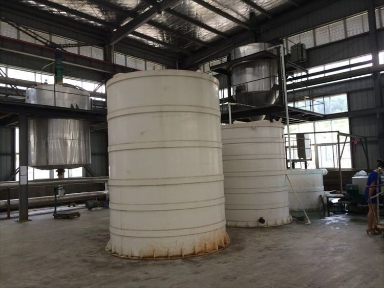
Density Measurement Chemical Processing Overview
Density measurement chemical processing is one of the most widely deployed process analytical technologies in chemical manufacturing, yet its potential is often underutilized due to poor instrument selection, suboptimal installation, or inadequate integration with the control system. This overview introduces the fundamental role of density measurement chemical processing operations and sets the context for the detailed application guidance that follows.
1. Why Density Measurement Matters in Chemical Processing
Density Measurement Chemical Processing Background
The traditional approach to process density monitoring is laboratory sampling: an operator takes a sample, carries it to the lab, and measures it with a hydrometer or digital density meter. The result is available 15-45 minutes after sampling.
In a typical chemical reactor operating at steady state, a 30-minute measurement lag means the process has moved on by the time you know what state it was in. The operator adjusts based on old information, producing off-spec product that may require reprocessing or disposal.
Inline density measurement eliminates this lag. The instrument sits in the process line, measuring every few seconds, and the control system responds to the actual current state of the process.
1.2 The Economic Impact
The business case for inline density measurement in chemical processing is quantifiable:
- Raw material savings: Tight concentration control reduces over-addition of expensive reactants
- Energy savings: Maintaining optimal process conditions reduces heating/cooling energy waste
- Yield improvement: Better process control means fewer batches of off-spec product
- Waste reduction: Fewer rejected batches means less hazardous waste for disposal
- Throughput improvement: Faster startup and grade changeover
Industry data from LONNMETER customer deployments shows typical payback periods of 3-8 months on inline density instrumentation.
2. Key Chemical Processing Applications
2.1 Acid Concentration Control
Sulfuric acid (H₂SO₄), hydrochloric acid (HCl), nitric acid (HNO₃), and phosphoric acid (H₃PO₄) are among the most common chemicals in which density-based concentration control is applied.
Why density? Each acid has a well-defined density-to-concentration relationship. Sulfuric acid’s density-concentration curve is highly non-linear between 50-100% concentration — making density an excellent indicator across the entire range. Small changes in concentration produce measurable changes in density.
Key applications:
| Acid | Concentration Range | Typical Accuracy Required | Recommended Instrument |
|---|---|---|---|
| Sulfuric acid | 50-100% | ±0.5% concentration | LONN-700CM or LONN-7000 |
| Hydrochloric acid | 20-38% | ±0.2% concentration | LONN-7000 (Hastelloy) |
| Sodium hydroxide | 20-50% | ±0.5% concentration | LONN-700CM |
| Nitric acid | 40-68% | ±0.5% concentration | LONN-7000 or LONN-700C |
2.2 Reactor Monitoring and Control
Chemical reactors — batch and continuous — are prime candidates for inline density monitoring.
Batch reactor applications:
- Reaction progress monitoring: As reactants are consumed and products formed, the density of the reaction mass changes. Tracking density versus time provides a real-time window into reaction progress without sampling.
- Endpoint detection: The density signal can be used to detect the reaction endpoint — the point at which the desired conversion has been achieved — enabling automatic reactor shutdown or transfer.
- Safety monitoring: Unexpected density changes can indicate side reactions, precipitation events, or contamination, triggering operator alerts.
Continuous reactor applications:
- PID concentration control: The density signal replaces (or supplements) laboratory measurements as the primary process variable for the reactant addition PID controller.
- Feed-forward control: Density measurement at the feed inlet, combined with measurement at the reactor outlet, enables feed-forward control strategies that respond to feed composition changes before they affect reactor performance.
2.3 Crystallization Control
Crystallization is a separation process in which a solute comes out of solution as crystals. The point at which crystallization begins (the supersaturation limit) is a strong function of solution density.
Inline density measurement enables:
- Supersaturation control: Maintaining supersaturation within the optimal window maximizes crystallization rate while avoiding uncontrolled nucleation
- Crystal size distribution control: Density correlates with slurry concentration, which determines the supersaturation driving force that controls crystal growth rate
- Yield optimization: The final mother liquor density at harvest indicates how much product was recovered versus how much remains dissolved
2.4 Liquid-Liquid Separation
In solvent extraction and decantation processes, density measurement at the liquid-liquid interface enables:
- Interface level detection: Density difference between the two liquid phases identifies interface position
- Phase purity monitoring: Density changes in the aqueous phase indicate solvent carryover (and vice versa)
- Separation efficiency control: Continuous density monitoring tracks separation performance and alerts operators to emulsion or carryover events
2.5 Blending and Formulation
Chemical blending operations — where multiple components are combined in precise proportions — rely on density as a primary feedback parameter:
- Concentration verification: Density confirms that the correct amount of each component was added
- Quality release: Batch density versus specification confirms product quality before release
- Mixing uniformity: Density uniformity across a mixing vessel confirms complete blending
2.6 Desalination and Brine Concentration
In brine concentration and zero liquid discharge (ZLD) systems, inline density monitoring tracks brine concentration through multiple evaporation stages — maximizing recovery while preventing scaling and fouling.
3. Measurement Challenges in Chemical Processing
3.1 Corrosive Fluids
Strong acids, alkalis, and chloride-containing solutions attack instrument materials. The primary failure mode is corrosion of wetted parts — leading to measurement error and potential leaks.
LONNMETER solution: The LONN-700CM ceramic density meter uses an Al₂O₃ ceramic sensor fork that is virtually immune to acid attack. For applications requiring Hastelloy wetted parts, the LONN-7000 ultrasonic instrument is available in Hastelloy construction.
3.2 High Temperature Processes
Many chemical processes operate at elevated temperatures — above 100°C, sometimes above 200°C. Standard density meters may not be rated for these conditions.
LONNMETER solution: The LONN-7000 is rated for process temperatures up to 200°C. The LONN-700S split-type design uses a remote transmitter to isolate electronics from high-temperature process environments.
3.3 Abrasive Fluids
Slurry-type chemical processes (e.g., pigment slurries, catalyst suspensions) contain suspended solids that can erode sensor surfaces.
LONNMETER solution: The LONN-7000 ultrasonic principle has no sensor surface in contact with the fluid — making it ideal for abrasive applications. The LONN-700CM ceramic fork is also highly resistant to mechanical abrasion.
3.4 Hazardous Areas
Many chemical processing plants operate in hazardous areas where flammable vapors or gases may be present. Density meters installed in these areas must carry appropriate explosion protection certification.
LONNMETER solution: All LONNMETER inline density meters are available with ATEX Ex d IIC T4 certification for Zone 1 hazardous area installation.
4. Implementation Guide
4.1 Installation Best Practices
Location selection:
- Install at a location where the fluid is well-mixed and representative
- Avoid locations near pumps, valves, or flow disturbances (high turbulence increases measurement noise)
- For batch reactors, install at the mid-tank level or in a by-pass loop
- Ensure adequate clearance for instrument housing and cable routing
Orientation:
- Tuning fork instruments: horizontal installation with fork tips pointing upward is preferred
- Ultrasonic instruments: follow manufacturer’s specific mounting requirements
Process connection:
- Use a full-port ball valve isolation fitting for by-pass installations (allows instrument removal without process shutdown)
- Ensure the process connection is properly sealed with compatible gasket material
4.2 Calibration and Validation
Initial calibration: Commission the instrument on the actual process fluid — not just water. The instrument’s calibration function allows zero and span adjustment using process samples verified against a laboratory reference.
Ongoing validation: Compare the inline reading against a laboratory measurement (taken simultaneously from the same sample point) at a regular interval — weekly or monthly depending on the application criticality. Log the comparison data for regulatory traceability.
Recalibration: Annual recalibration by the manufacturer or an accredited calibration laboratory is recommended for most applications. LONNMETER offers traceable calibration certificates.
4.3 Control Integration
4-20mA integration:
- Connect the instrument’s 4-20mA output to a DCS analog input
- Configure the DCS scaling (mA to density units) using the instrument’s calibration certificate
- Configure high/low alarms in the DCS for density out-of-spec events
Modbus integration:
- Connect the RS-485 Modbus-RTU output to the DCS via a serial port or gateway
- Poll density (register address), temperature, and alarm status
- Use Modbus for multi-instrument networking (multiple instruments on one bus)
PID control:
- Use the density signal as the primary process variable (PV) for the PID controller
- Configure the setpoint (target density/concentration) based on process requirements
- Tune the PID loop with the instrument online — allow 2-4 weeks for the loop to stabilize
Common Chemical Processing Density Measurement Mistakes to Avoid
Even with the best intentions, density measurement chemical processing installations frequently fail to deliver their potential due to predictable, avoidable errors. Understanding these common mistakes before you specify or install an instrument can save significant cost and frustration.
Mistake 1: Specifying accuracy that exceeds your actual requirement. It is tempting to specify the most accurate instrument available, but accuracy has a cost — both in instrument price and in installation complexity. For most density measurement chemical processing applications — acid concentration control, blending operations, crystallization monitoring — ±0.001 g/cm³ accuracy is more than sufficient. Specifying ±0.0005 g/cm³ accuracy when you only need ±0.005 g/cm³ means paying 2-3× more for precision that your process cannot use. The key is to match accuracy to your process specification tolerance, not to the best number you can find on a specification sheet.
Mistake 2: Ignoring temperature compensation. Fluid density changes with temperature — and in chemical processing, temperature variations of 20-50°C are common. Without proper temperature compensation, your density reading will drift with temperature changes even if the actual concentration is stable. All LONNMETER density meters include built-in PT100 temperature sensors with automatic temperature compensation to a reference temperature (typically 20°C). When specifying instruments for density measurement chemical processing applications, always confirm that temperature compensation is included and that the reference temperature matches your process requirements.
Mistake 3: Installing in the wrong location. The best instrument in the wrong location will give poor results. Common installation errors include: placing the instrument near a pump or valve (where flow disturbances create measurement noise); installing in a dead leg or low-flow zone (where the fluid is not representative of the process); and failing to account for stratification in tanks (where density varies vertically). For density measurement chemical processing applications, the ideal installation is in a well-mixed section of the process line, at a location where the fluid is representative of the bulk process stream.
Mistake 4: Failing to validate on the actual process fluid. Every chemical has a unique density-to-concentration relationship. Calibrating an instrument on water and then using it to measure sulfuric acid will introduce errors because the instrument’s response characteristics differ between fluids. Always commission the instrument on the actual process fluid — or at minimum, validate the reading against a laboratory reference on the actual process fluid before relying on it for process control.
Mistake 5: Not planning for maintenance. Density meters require periodic calibration and occasional sensor cleaning or replacement. Planning the installation to allow instrument removal without process shutdown — using a by-pass loop with isolation valves — is essential for critical applications. A density meter that requires a full process shutdown for every calibration will quickly become a source of production losses rather than a source of process improvement.
By avoiding these five common mistakes, your density measurement chemical processing installation will deliver the real-time monitoring and control improvements that justify the investment.
5. Frequently Asked Questions
Q: Can an inline density meter handle concentrated sulfuric acid at 98%? A: Yes. Concentrated sulfuric acid is a common application for inline density measurement. The LONN-700CM ceramic density meter is highly recommended for this application — the Al₂O₃ ceramic sensor fork is virtually immune to attack by concentrated sulfuric acid. The Hastelloy version of the LONN-7000 is also suitable for H₂SO₄ applications. Ensure the instrument is specified for the full concentration range you will encounter, including any dilute acid handling during cleaning cycles.
Q: How do I account for temperature effects on density measurement? A: All LONNMETER density meters include built-in PT100 temperature sensors and automatic temperature compensation to a reference temperature (typically 20°C). The instrument outputs the temperature-compensated density reading — meaning the density value is corrected to what it would be at 20°C, regardless of the actual process temperature. This is the standard approach for concentration measurement and should be specified for all chemical processing applications.
Q: Can I use one density meter to measure multiple chemicals in a multi-product plant? A: If the chemicals are non-reactive with each other and the instrument’s wetted materials are compatible with all process fluids, yes — but the density-to-concentration conversion will differ for each chemical. The instrument will output density (in g/cm³), and your DCS will need to apply the appropriate conversion formula for each product. LONNMETER can provide the conversion table for each chemical as part of the application specification. For highly reactive or incompatible chemical combinations, dedicated instruments are required.
Q: What is the expected response time for density-based PID control? A: The LONN-7000 and LONN-700CM both have response times of less than 1 second (typically 0.3-0.5 seconds). This is fast enough for most PID control applications in chemical processing. For very fast-responding processes (e.g., inline mixing control with time constants of seconds), the instrument’s response time is unlikely to be the limiting factor.
Q: How do I validate the density measurement against laboratory results? A: Take a simultaneous sample from the same location as the inline instrument while the process is at steady state. Measure the sample in your laboratory with a calibrated reference instrument (hydrometer or digital density meter). Compare the laboratory result against the inline instrument’s output at the time of sampling. The difference is your measurement error. Repeat this comparison at least 5 times across the normal operating range. If the error is within your specification, the inline instrument is validated. If not, recalibrate or investigate the installation location.
6. Featured Products for Chemical Processing
| Product | Principle | Key Feature | Chemical Application |
|---|---|---|---|
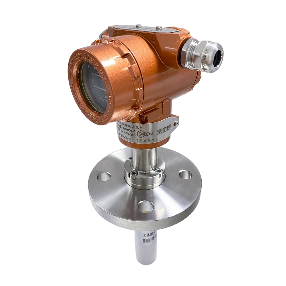
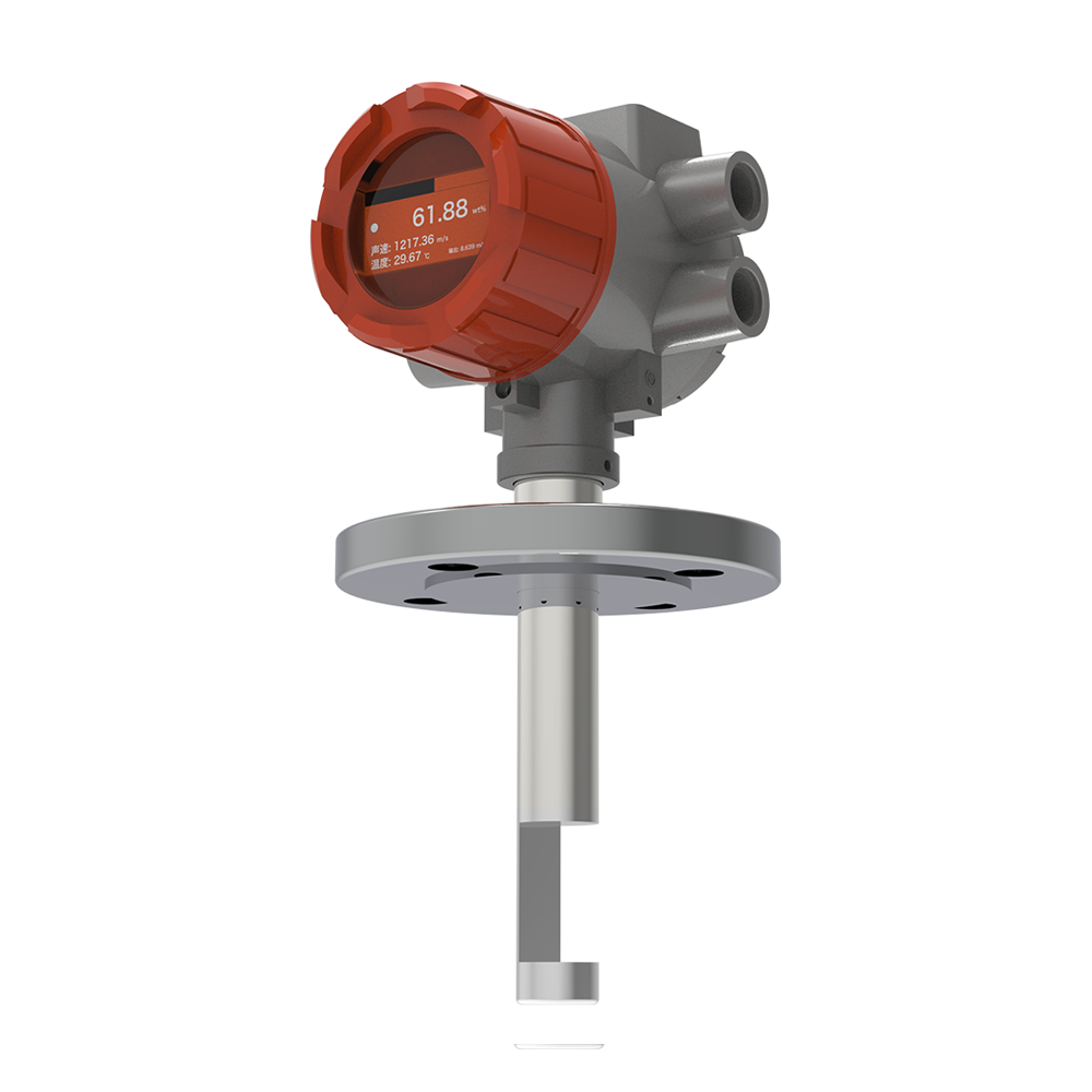
| LONN-7000 | Ultrasonic | Non-nuclear, Hastelloy option | H₂SO₄, HCl, caustics |
| LONN-700CM | Tuning Fork, Ceramic | Al₂O₃ ceramic fork | All acids, abrasive slurries |
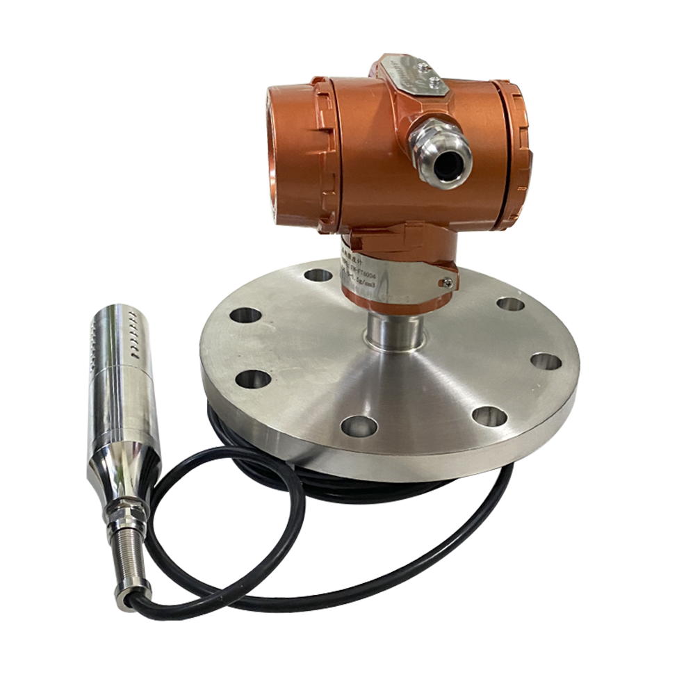
| LONN-700S | Tuning Fork, Split | Remote transmitter | High-temperature processes |
| LONN-700C | Tuning Fork, Standard | 316L construction | General chemical |
Request a Quote
To discuss your chemical processing density measurement application, LONNMETER offers free application evaluation and on-site trial capability.
Contact: anna@xalonn.com