From Wellhead to Custody Transfer: The Complete Upstream Measurement Journey
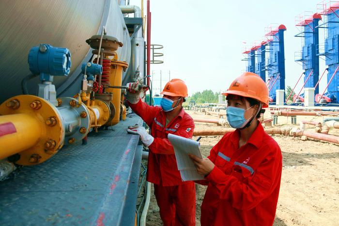
Every barrel of crude oil that reaches a refinery began its journey at a wellhead — somewhere between 1,000 meters and 5,000 meters underground, flowing through a production string, entering a separator, traveling through gathering lines, accumulating in storage tanks, and finally metered at the custody transfer point where ownership passes from producer to midstream operator.
Each stage of this journey presents a distinct measurement challenge. At the wellhead, the fluid is a multiphase mixture of oil, water, and gas — with composition that changes as the reservoir depletes. In the separator, density measurement determines the oil-water interface level and the efficiency of phase separation. In the pipeline, viscosity determines the pumping energy required and the minimum flow velocity to prevent wax deposition and flow assurance problems. At the custody transfer point, density measurement determines the API gravity — the basis for crude oil valuation and commercial settlement.
The LONNMETER upstream oil gas solution addresses every measurement point along this journey — from wellhead to pipeline to custody transfer — with instrumentation engineered for hazardous area operation, continuous unattended service, and the temperature and pressure extremes characteristic of upstream production environments.
Section 1: Wellhead and Separator Operations in the Upstream Oil Gas Solution
The upstream oil gas solution begins at the production face. The Measurement Challenge at the Production Face
At the wellhead, crude oil is not a pure hydrocarbon fluid. Production fluids from most reservoirs are multiphase mixtures: crude oil (typically 70-95% by volume), produced water (5-30%), and associated gas (0-10% dissolved or free gas). As the reservoir matures, the water cut increases — some fields produce 90% water and only 10% oil by volume in their later production life.
The production separator (or test separator for individual well testing) separates these phases using gravity settling and density difference. The oil-water interface level in the separator is controlled by a level control valve — but the interface level control requires accurate density measurement of the oil and water phases, which change continuously as well production rates vary and as different wells are routed to the separator.
Density Measurement for Separator Efficiency
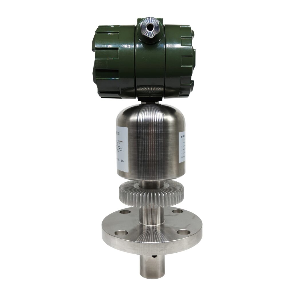
The LONN-700S split-type tuning fork density meter is installed at the oil outlet and water outlet of the separator. The split-type design — with the electronics housing separated from the wetted fork sensor by a 5-15 meter cable — is critical for separator installations where the separator vessel is located in a hazardous area (Zone 1 or Zone 2) but the electronics housing must be accessible for calibration and maintenance without vessel entry.
The LONN-700S provides continuous density measurement with ±0.001 g/cm3 accuracy of the oil phase (typically 800-950 kg/m³ for crude oil) and water phase (1,000-1,100 kg/m³ for produced water with dissolved salts). The density signals feed the separator interface level control system, which adjusts the water draw-off valve to maintain the oil-water interface at the optimal level for phase separation.
Performance requirement: Separator oil-water interface control requires density measurement accuracy of approximately ±2-5 kg/m³ (±0.002-0.005 g/cm³). The LONN-700S ±0.001 g/cm³ accuracy exceeds this requirement, enabling tighter interface control and reduced oil-in-water or water-in-oil contamination.
Heavy Oil: Viscosity at the Wellhead
Heavy oil production (API gravity below 20, viscosity above 200 cP at reservoir temperature) presents a different measurement challenge. Heavy oil viscosity determines the production rate that can be achieved with artificial lift (rod pump, progressing cavity pump, or electric submersible pump), the injection rate for enhanced oil recovery (EOR) steam or solvent injection, and the heating requirement for viscosity reduction.
The LONN-DN60 high-viscosity inline viscometer is installed in the wellhead flowline for heavy oil production monitoring. The 0-5,000,000 cP measurement range covers the full viscosity range of heavy oil and bitumen production, including viscosity variations due to temperature cycling (night to day temperature variations in surface pipelines) and due to EOR injection variations (steam-to-oil ratio changes in cyclic steam stimulation).
Field installation note: For heavy oil wellhead installations, the LONN-DN60 sensor body is typically specified in 316L stainless steel with optional wear-resistant coating (tungsten carbide or ceramic) for crude oils with high sand content (heavy oil production often includes 0.1-5% sand by volume from unconsolidated formations).
Section 2: Pipeline Operations in the Upstream Oil Gas Solution
Pipeline Transportation: Flow Assurance and Viscosity Management
From the separator, crude oil enters the gathering pipeline system — a network of pipelines ranging from DN100 (4-inch) flowlines from individual wells to DN600 (24-inch) trunk lines from production batteries to the central processing facility or custody transfer point.
In light crude production (API 30-40, viscosity 5-50 cP), pipeline transportation is relatively straightforward: the crude oil flows easily, the pumping energy requirement is moderate, and wax deposition is minimal. In medium crude production (API 20-30, viscosity 50-500 cP), viscosity begins to affect pumping energy and may require heating or diluent injection. In heavy crude production (API 10-20, viscosity 500-100,000+ cP), viscosity is the dominant parameter for pipeline design and operation.
Flow assurance: Heavy crude pipelines require continuous viscosity monitoring to detect wax deposition (which increases effective viscosity) and to optimize the heating or diluent injection rate. The LONN-ND80 tuning fork viscometer, with ±1% full-scale viscosity accuracy and simultaneous density measurement capability, provides the dual-parameter monitoring required for heavy oil pipeline flow assurance: viscosity for pumping energy optimization, density for diluent ratio control (when diluent is injected for viscosity reduction).
Non-Intrusive Flow Measurement for Existing Pipelines
Many gathering system pipelines were installed without flow measurement provisions — no flow meter in the original design, no provision for a meter run (straight pipe lengths upstream and downstream), and no opportunity for process shutdown to install a meter. For these existing pipelines, clamp-on ultrasonic flow measurement is the only practical solution.
The LONN-UFM clamp-on ultrasonic flow meter installs on the outside of the pipe, measuring flow through the pipe wall without any process penetration. The transit-time ultrasonic principle requires only access to the pipe OD surface for sensor mounting. Installation time is typically 1-2 hours per measurement point, with no process shutdown required. After installation, the LONN-UFM provides continuous flow measurement with accuracy of approximately ±2% of reading (for properly installed clamp-on measurement on straight pipe with known pipe wall thickness and material).
Pipe size range: The LONN-UFM covers pipe sizes from DN6 (0.25-inch) to DN6000 (240-inch), making it suitable for everything from wellhead flowlines (DN50-100) to trunk pipelines (DN300-600). The IP65/IP67 protection rating enables outdoor installation without additional weather protection.
Pipeline Custody Transfer: Density and API Gravity
At the custody transfer point — where crude oil ownership passes from the producer to the midstream pipeline operator or to the purchaser — density measurement determines the API gravity, which determines the crude oil value under most purchase contracts. A crude oil priced at $70 per barrel with a 10 cent per barrel API gravity differential has a $7,000 value exposure for a 100,000 barrel cargo if the API gravity is mis-measured by 0.5 API degrees.
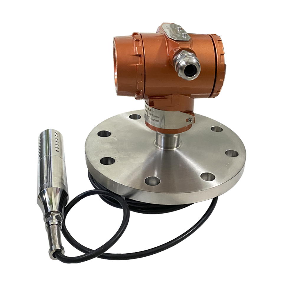
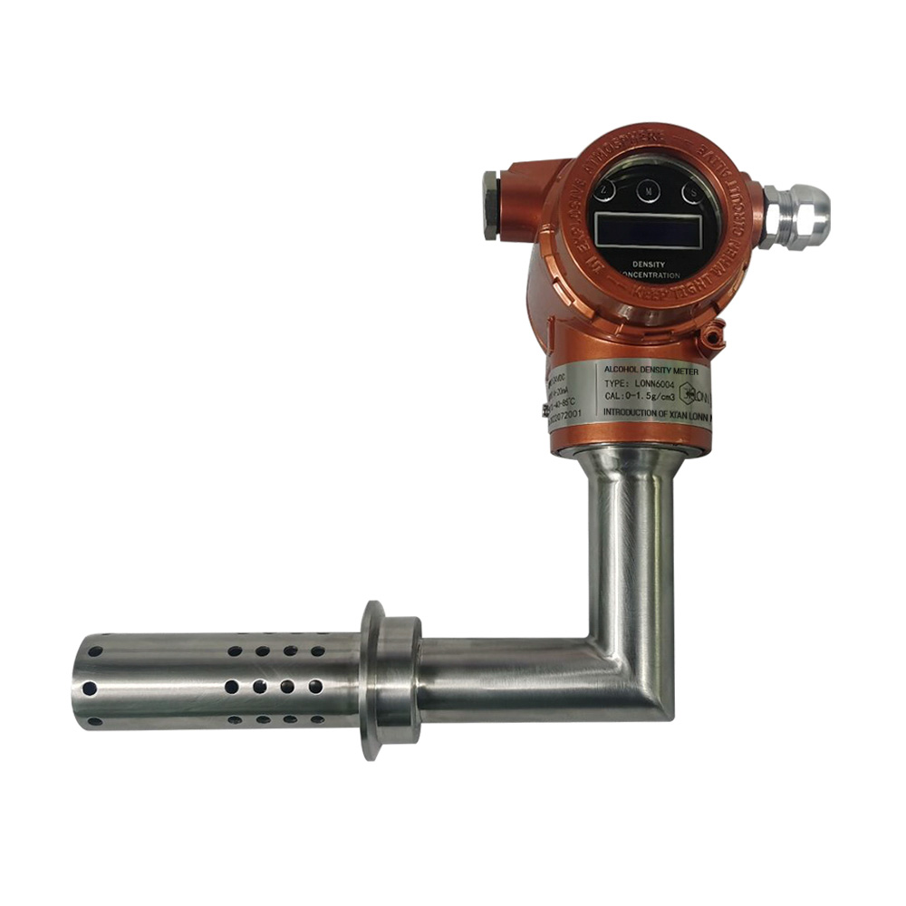
The LONN6004 U-tube oscillating density meter provides the ±0.001 g/cm³ accuracy required for custody transfer API gravity measurement. The oscillating U-tube principle — the same principle used in ASTM D4052 laboratory density measurement — provides direct traceability between the inline measurement and the laboratory reference method. The built-in PT100 temperature sensor (±0.1°C accuracy) provides the temperature measurement required for API gravity correction to standard conditions (60°F or 15°C).
Section 3: Storage Operations in the Upstream Oil Gas Solution
Tank Farm Density Stratification
Crude oil storage tanks accumulate fluid over time, with successive cargo receipts potentially having different densities (different wells, different reservoir zones, different crude oil grades). Over time, the tank develops density stratification: lighter crude oil (lower density, higher API gravity) floats on top of heavier crude oil (higher density, lower API gravity), with potential emulsion and water layers at intermediate levels.
Density stratification affects tank gauging accuracy (if the tank gauge assumes a uniform density throughout the tank volume) and affects product quality when the tank is drained into a pipeline or loading line (the crude oil density changes during the tank draw-down as different density layers are withdrawn).
The LONN-700S split-type fork density meter can be installed at multiple levels in the storage tank (for example: 1 meter from bottom, 5 meters from bottom, 9 meters from bottom for a 10-meter tank) to measure the density profile and detect the oil-water interface level. The density profile data enables accurate tank inventory calculation and enables the operator to identify when the tank draw-down is approaching the water draw-off level.
Loading Line Viscosity and Density Monitoring
For tanker loading operations (crude oil export by ship) and pipeline loading operations (crude oil dispatch to a refinery or pipeline terminal), the loading line density and viscosity measurement provides quality verification for the cargo being loaded.
The LONN-ND80 tuning fork viscometer, installed in the loading line, provides simultaneous density and viscosity measurement in a single instrument. This dual-parameter capability is particularly valuable for crude oil loading: density provides API gravity for cargo documentation, viscosity provides quality verification for heavy crude cargoes (where the purchaser may specify viscosity limits in addition to API gravity limits).
Installation location: The LONN-ND80 is typically installed 10-20 diameters downstream of the loading pump discharge, where the flow profile is fully developed and the temperature is representative of the cargo temperature. The ATEX Ex d IIC T4 certification covers Zone 1 hazardous area installation at the loading berth or pipeline terminal.
Instrument Selection for the Upstream Oil Gas Solution
| Process Stage | Primary Measurement | Recommended Instrument | Key Specification |
|---|---|---|---|
| Wellhead | Multiphase fluid density | LONN-700S split-type fork | ±0.001 g/cm³, Ex d IIC T4, 5-15m cable |
| Wellhead (Heavy Oil) | Viscosity for EOR control | LONN-DN60 high-viscosity | 0-5,000,000 cP, 300°C max, wear-resistant coating option |
| Separator | Oil/water density for interface | LONN-700S split-type fork | Split electronics for vessel installation |
| Gathering Pipeline | Flow rate (non-intrusive) | LONN-UFM clamp-on ultrasonic | DN6-DN6000, ±2% accuracy, IP65/67 |
| Gathering Pipeline (Heavy Oil) | Viscosity + density for flow assurance | LONN-ND80 tuning fork | 0.5-5,000 cP viscosity, ±0.001 g/cm³ density |
| Custody Transfer | API gravity density | LONN6004 U-tube oscillating | ±0.001 g/cm³, Ex d IIC T6, PT100 temp |
| Storage Tank | Density profile/stratification | LONN-700S split-type fork | Multiple level installation option |
| Loading Line | Cargo density + viscosity | LONN-ND80 tuning fork | Dual-parameter from single sensor |
Field-Proven Results from the Upstream Oil Gas Solution
Result 1: Heavy Oil Pipeline Flow Assurance Optimization
Field: A heavy oil production field in Alberta, Canada, producing 15,000 barrels per day of 14 API gravity crude oil from cyclic steam stimulation (CSS) wells. The crude oil viscosity varied from 2,000 cP to 50,000 cP depending on the steam-to-oil ratio and the time since the last steam injection cycle.
Problem: The pipeline operator used a fixed heating rate for the pipeline heater, based on the assumption of maximum viscosity. During periods of lower viscosity (following steam injection), the pipeline was over-heated, wasting fuel gas. During periods of higher viscosity (late in the CSS cycle), the pipeline temperature was sometimes insufficient, causing pumping pressure to exceed the pump rating.
Solution: Two LONN-ND80 tuning fork viscometers installed in the pipeline heater inlet and outlet. The viscosity signals fed the heater firing control system, which adjusted the heater firing rate to maintain target viscosity (5,000 cP) at the pipeline pump suction.
Outcome:
- Fuel gas consumption reduced by 18% (heater no longer over-fired for low-viscosity periods)
- Pump pressure excursions eliminated (heater automatically increased firing for high-viscosity periods)
- Payback period: 11 months (fuel gas savings only)
Result 2: Separator Interface Control Improvement
Field: An offshore production platform in the North Sea, processing 80,000 barrels per day of crude oil from multiple wells through two-stage separation (HP separator and LP separator). The crude oil density varied from 820 to 890 kg/m³ depending on which wells were in production.
Problem: The separator interface level control used capacitance-based level sensors, which required frequent calibration adjustment as the crude oil density changed. When the calibration was not adjusted promptly after a well changeover, the interface level control became unstable, causing water carryover to the crude oil export line (customer specification: <0.5% water) or oil carryover to the produced water treatment system (environmental specification: <30 ppm oil-in-water).
Solution: LONN-700S split-type density meters installed at the oil outlet and water outlet of each separator. The density signals fed the interface level control system, which used density difference to calculate the interface position rather than relying on a fixed capacitance calibration.
Outcome:
- Water carryover to export line reduced from an average of 0.8% to 0.3% (within specification)
- Oil carryover to produced water reduced from 80 ppm average to 25 ppm (within specification)
- Interface level control stability improved — no manual calibration adjustments required after well changeover
Result 3: Pipeline Custody Transfer Density Measurement
Field: An onshore crude oil gathering system in West Texas, gathering 120,000 barrels per day from 40 individual leases to a central custody transfer point. The crude oil gravity ranged from 35 API to 42 API depending on the lease.
Problem: The custody transfer density measurement used an online densitometer with ±0.005 g/cm³ accuracy. When compared to the purchaser’s tank gauge measurement at the receiving terminal (±0.0005 g/cm³ repeatability), the density difference resulted in crude oil volume mismatches averaging 0.3% — equivalent to 360 barrels per day or approximately $25,000 per day at $70/barrel crude oil price.
Solution: LONN6004 U-tube oscillating density meter installed at the custody transfer point, replacing the legacy densitometer. The ±0.001 g/cm³ accuracy reduced the density measurement uncertainty component of the custody transfer volume mismatch.
Outcome:
- Density measurement accuracy improved from ±0.005 g/cm³ to ±0.001 g/cm³
- Volume mismatch with purchaser’s measurement reduced from 0.3% average to 0.08% average
- Financial exposure from measurement dispute reduced by approximately $17,000 per day
Questions on the Upstream Oil Gas Solution
What density accuracy is required for custody transfer crude oil measurement?
For crude oil custody transfer, the density accuracy requirement depends on the custody transfer contract terms and the regulatory framework (API MPMS in North America, international standards elsewhere). A typical requirement is ±0.001 g/cm³ (approximately 0.2 API gravity) for fiscal custody transfer measurement.
The LONN6004 U-tube oscillating density meter provides ±0.001 g/cm³ accuracy, meeting the repeatability requirements of API MPMS Chapter 9.2 for Class A meters. For custody transfer applications, confirm the specific requirements of your crude oil purchase contract and the calibration traceability requirements (NIST traceability in the United States, national metrology institute traceability internationally).
Can inline viscosity measurement replace laboratory testing for heavy oil pipeline operations?
For heavy oil pipeline operations, inline viscosity measurement provides real-time data for process control (heater firing rate, pump speed, diluent injection rate). The LONN-ND80 and LONN-DN60 tuning fork viscometers provide ±1-3% full-scale accuracy under dynamic calibration conditions.
However, most heavy oil pipeline tariffs and crude oil purchase contracts specify viscosity measurement per ASTM D445 (kinematic viscosity, laboratory rotational viscometer). For contractual compliance, laboratory testing per ASTM D445 is still required. The inline viscosity measurement provides process control data between laboratory tests and enables immediate detection of viscosity excursions that would not be discovered until the next laboratory test.
For non-contractual applications (internal process control, flow assurance monitoring, EOR optimization), inline viscosity measurement can replace routine laboratory testing — with periodic laboratory verification for calibration audit purposes.
What is the installation requirement for clamp-on ultrasonic flow measurement?
The LONN-UFM clamp-on ultrasonic flow meter requires access to the outside surface of the pipe at two positions (upstream sensor and downstream sensor, typically separated by 0.5-2 pipe diameters depending on pipe size and flow velocity). The installation requirements are:
- Straight pipe: Minimum 10 diameters of straight pipe upstream, 5 diameters downstream (for fully developed flow profile)
- Pipe surface condition: Clean, bare metal or consistent coating thickness. Remove rust, scale, or loose paint at sensor mounting positions
- Pipe parameters known: Pipe OD, wall thickness, and material must be known for accurate flow calculation
- Fluid parameters known: Fluid velocity range, fluid type (crude oil, water, gas), and approximate fluid density for signal strength optimization
Installation time is typically 1-2 hours per measurement point. No process shutdown, no pipe cutting, and no hot work permit required (sensors mount externally with coupling gel or permanent adhesive).
How does density measurement improve separator interface control?
The oil-water interface in a separator exists at the density level where oil (lower density, typically 800-950 kg/m³) meets water (higher density, typically 1,000-1,100 kg/m³). Traditional interface level control uses capacitance or microwave level sensors, which measure the interface position based on the dielectric difference between oil and water — but require calibration for the specific oil and water densities.
When the crude oil density changes (different wells in production, reservoir composition variation), the dielectric constant of the oil phase also changes, requiring recalibration of the interface sensor. If recalibration is delayed, the interface control becomes inaccurate — water carryover to the oil outlet or oil carryover to the water outlet.
Density-based interface control measures the density of the oil outlet stream and the water outlet stream directly. The interface level is inferred from the oil and water densities and the total liquid level in the separator. This approach is inherently robust to crude oil density variations — no recalibration required when well composition changes.
What maintenance is required for density and viscosity meters in upstream service?
LONN-700S tuning fork density meter: The tuning fork sensor has no moving parts and no seals. The only maintenance is periodic calibration verification (recommended: every 12 months for process control applications, every 6 months for custody transfer applications). In heavy oil service with sand production, inspect the fork surface for erosion annually and specify wear-resistant coating for high-sand applications.
LONN6004 U-tube density meter: The oscillating U-tube requires periodic cleaning if the process fluid deposits scale, wax, or solids on the inner surface of the tube. For crude oil service, a solvent flush or hot oil flush every 6-12 months is typically sufficient. Calibration verification recommended every 6 months for custody transfer.
LONN-ND80 and LONN-DN60 viscometers: Tuning fork design with no rotating seals, no bearings, and no process obstructions. Maintenance is limited to calibration verification (every 6-12 months depending on application criticality). In heavy oil with sand, specify wear-resistant coating for the fork surface.
Get Your Upstream Oil Gas Solution
Every upstream oil gas solution deployment addresses unique measurement challenges — reservoir fluid characteristics, production rates, artificial lift methods, gathering system configuration, and custody transfer requirements. LONNMETER application engineers with direct upstream production experience work with your team to identify the optimal measurement solution for each stage of your wellhead-to-custody-transfer journey.
Information to prepare:
- Reservoir fluid characteristics (API gravity range, viscosity range, GOR, water cut trend)
- Production configuration (well count, artificial lift method, separator stages)
- Gathering system (pipeline diameters, distances, heating/diluent requirements)
- Custody transfer specification (accuracy requirement, measurement standard, calibration traceability)
- Hazardous area classification at each measurement location
Email: anna@xalonn.com
LONNMETER — smartmeasurer.com
Fill out our RFQ form