The unit left our bench reading ±0.001 g/cm³ against distilled water. Two weeks later it was drifting by five times that on the customer's line, and the first email blamed the sensor.

It was not the sensor. Someone had mounted it six pipe diameters off a slurry pump, on the top of a horizontal run, where the pipe never ran full and the air went looking for the probe. The bench test could not see that. This inline density meter installation guide exists because the install point decides the number more often than the datasheet does — and because picking the right model and placing it right are the same job, not two. A correct inline density meter installation starts with selection, not after it.

If you are still choosing a technology, our inline measurement methods guide lays out the main techniques before you commit. Read that first if you have not. The rest of this article assumes you are ready to put steel in the pipe.

Why installation decides the number

Most field complaints we investigate trace back to the install, not the instrument. A tuning fork or ultrasonic cell measures what is actually at its face — and the fluid at the face is not always the fluid in the pipe. Turbulence, trapped air, an uneven flow profile, or a strand of pipe that only runs full at high flow will all write themselves into your density trend.

That is the first lesson of any inline density meter installation: the sensor is only as good as the few meters of line around it. Spend the selection effort, then spend equal effort on where it sits — a clean weld, a sound flange face, and a quiet ground point matter as much as the datasheet.

Step 1 — Choose the measurement technology

Three technologies cover the large majority of inline density duties. Pick on the fluid and the duty, not on which brochure you read last.

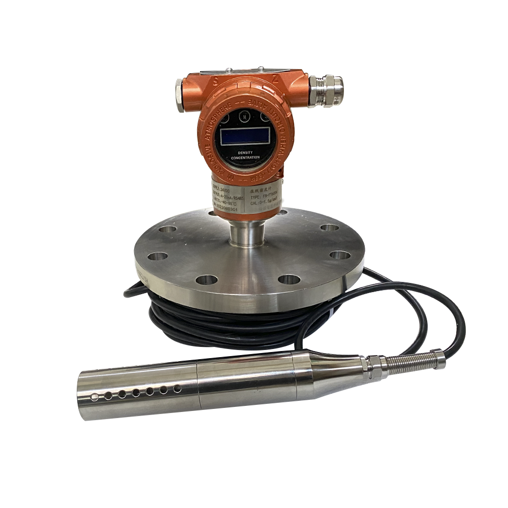
Tuning fork. A slender paddle vibrates in the liquid; denser product pulls the frequency down. It is compact, tolerant of flow and bubbles, and accurate to the level most processes need. Our tuning-fork density meter explainer walks through the physics. On our LONN-700C family, accuracy runs ±0.002 g/cm³ with repeatability near ±0.0002 per the LONN-700CM manual — far tighter than most process specs ask for.

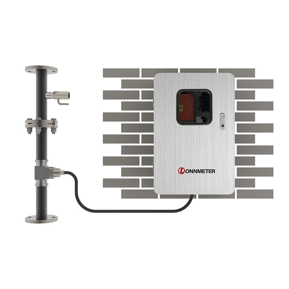
Ultrasonic. This method times a sound pulse through the product and infers density from acoustic velocity, and it can track concentration at the same time. It suits lines where the sensor should sit flush with the wall or clamp onto the outside. Our ultrasonic density meter article covers the LONN7000 family, which carries dual 4–20 mA outputs, RS485, and IP65 hardware built for washdown and damp locations.

Coriolis. A Coriolis instrument reads density as a by-product of mass flow, so it excels where you are already buying one for the flow duty. If density is the only goal, a dedicated fork or ultrasonic cell usually wins on cost. Our Coriolis density meter piece covers the trade in detail.

When the choice is genuinely close, our density meter selection guide gives a structured way to decide. The short version: match the technology to viscosity, aeration, hygiene, and whether flow measurement comes along for the ride.

Step 2 — Pick the mounting style

The mounting style is part of the inline density meter installation plan, because it changes what the line has to carry.

  • Insertion. A probe enters through a ball valve or flange and reaches into the flow. It is light, often hot-tappable, and easy to service without cutting the line. On abrasive or high-viscosity streams it lets you pull the fork for cleaning without a shutdown.
  • Inline (full-bore). The sensor sits in a spool piece welded or flanged into the line. The flow profile is the cleanest and the measurement the most representative, at the cost of a heavier body and a cut-in to fit it.
  • Clamp-on (ultrasonic only). Nothing wetted, nothing to drill. You trade some accuracy and a sensitivity to pipe scale and coupling for zero process intrusion. It is the right answer on lines you cannot cut and streams you would rather not touch.

Step 3 — Find the right install point

Before any inline density meter installation, walk the line before you cut it. This is the part of the inline density meter installation guide that actually saves the project. The rules are boring and they are non-negotiable:

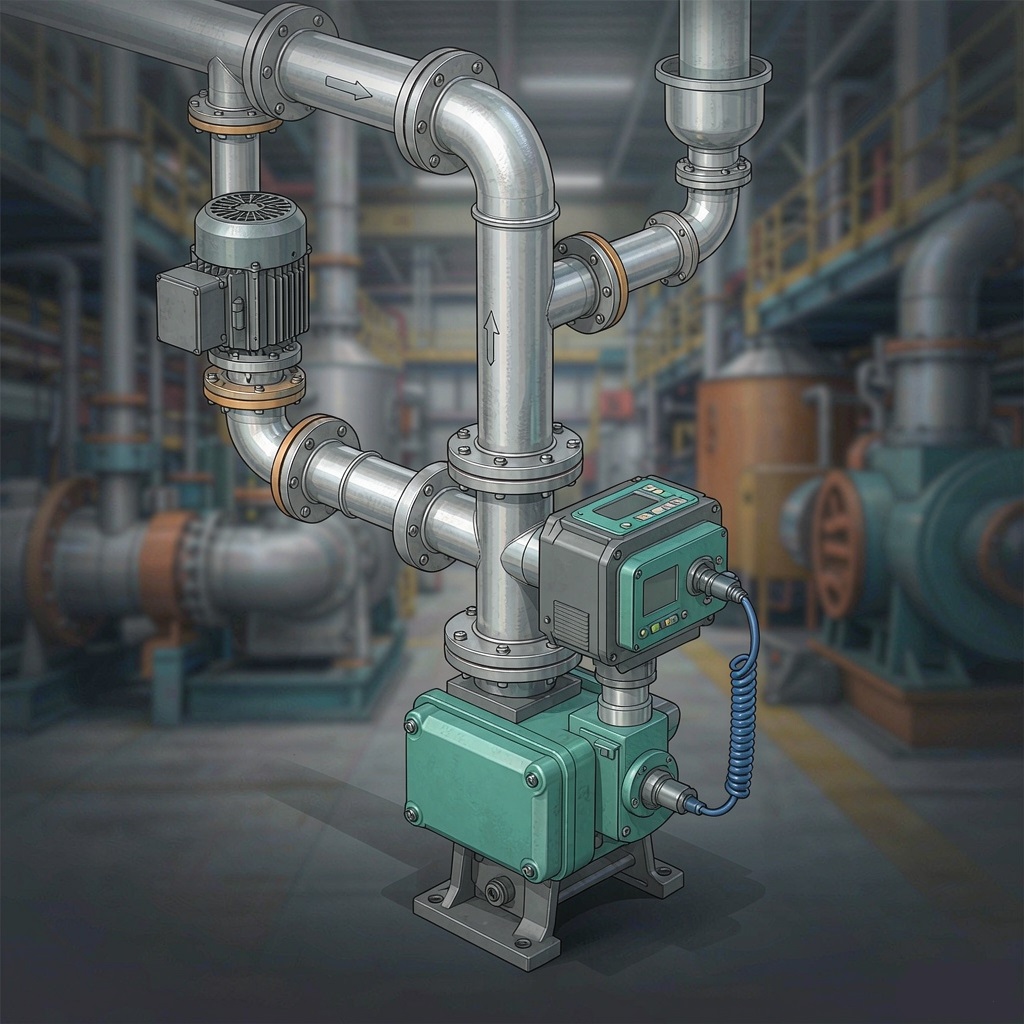
  1. Give it straight pipe. Place the sensor 10 to 15 pipe diameters downstream of any pump, valve, elbow, or reducer, and at least 5 diameters upstream of the next disturbance. A nearby manifold or tee counts as a disturbance too. Turbulence from a bend does not settle in two diameters; it needs a span to steady.
  2. Keep the pipe full. A sensor in a line that only runs full at high flow will read air part of the day. Vertical upward runs are the friendliest, because gravity keeps the run charged and helps bubbles escape instead of collecting at the probe.
  3. Stay off the top of horizontal runs. Air rises. Mounting on the crown of a horizontal pipe is how you measure the bubble fraction instead of the product.
  4. Sample after the blend point. Put the sensor downstream of where two streams actually finish mixing, not before. A reading taken in the unmixed layer is a reading of nothing useful.
  5. Let it de-aerate. After a high-shear mixer or a drop, give the fluid a chance to shed entrained air before it reaches the cell. Bubbles bend both a vibration path and an acoustic path.
  6. Think about the clean-out. If the line is cleaned in place, the sensor face has to see wash velocity on every cycle. A dead leg beside the sensor is a hygiene finding wearing a stainless disguise.
inline density meter installation

Fig. 1 — The install point that works. A flange-insertion density transmitter on a vertical upward run, set well downstream of the pump and elbow, with straight pipe to settle the profile and a path for air to clear.

Step 4 — Process connection, hygiene, and dead legs

For food, beverage, or pharma lines the inline density meter installation connection is a compliance item, not a detail. Use hygienic clamp or flange fittings, polished wetted surfaces, and a body that presents no dead volume where soil can shelter. The sensor must see CIP velocity on its face every cycle — caustic and acid at 1.5 to 2.5 m/s, often above 70°C — or it becomes a spare part that happens to measure things.

Even on rugged industrial lines, fewer crevices means less to foul and less to explain to an inspector. The cheapest install is the one you never have to defend.

Step 5 — Wiring, grounding, and the signal
The signal side of the inline density meter installation is where compliance lives, and the reading is only useful if it lands somewhere trustworthy. A 4–20 mA loop into the PLC is table stakes; RS485 carries the diagnostics and temperature that the loop alone does not. Ground the shield at one end only — grounding both ends is how you invite a ground loop and a reading that breathes with the plant load.

And put a timestamp on it. A density value in the batch record, with the product temperature logged alongside it, is what turns a measurement into evidence. The compliance story in a food or excise audit lives or dies on that timestamp, not on the sensor’s spec sheet.

tuning fork density meter

Fig. 2 — Tuning-fork density transmitter (LONNMETER, site photo). Slender wetted fork, compact body, insertion or flange mounting. Accuracy ±0.002 g/cm³ on the LONN-700C family per the LONN-700CM manual.

product ultrasonic system

Fig. 3 — Ultrasonic density system (LONN7000 family, site photo). Flush or clamp-on acoustic path, dual 4–20 mA plus RS485, IP65 for washdown and damp duty.

The install mistakes that quietly ruin readings

Every inline density meter installation we revisit shows the same five errors.

  • Mounting on pump suction. Low pressure there pulls air out of solution and starves the cell.
  • Crowning a horizontal run. The probe measures the air blanket instead of the product.
  • Sitting right after an elbow or valve. The flow profile is still fighting itself; the number wanders.
  • Trapping air after a mixer or drop. Entrained bubbles bend the measurement path; give them room to leave.
  • Skipping the temperature log. Density is temperature-sensitive; a reading with no product temperature attached is half a measurement.
  • Double-grounding the signal cable. Two ground points make a loop, and the loop makes noise that looks like process variation.

None of these is a sensor fault. All of them are fixable at the install stage, which is the whole point of doing the inline density meter installation properly rather than quickly.

What the group behind the instrument changes

Readers of this blog know us as an instrument maker, and that is true, but it is only part of the picture. LONNMETER designs the fork sensor, machines the bodies, winds and calibrates the electronics, and builds the washdown ultrasonic systems in our own facilities — then fields application engineers who spend their weeks inside process plants rather than showrooms. Design, R&D, production, and solution delivery sit under one roof, so the person who recommends your install point can walk twenty meters and ask the calibration technician a question. That shortens the distance between “the manual says” and “your line will do.”

If you are scoping an install and would rather not guess at the straight-pipe length or the mounting style, tell us the fluid, the pipe size, and the duty — the conversation is faster when it starts from your actual line. Our general density measurement hub collects the rest of the technical guides if you would rather read first and call later.

Frequently asked questions

Where should an inline density meter be installed on a pipe?

On a straight, full run — 10 to 15 pipe diameters downstream of any pump, valve, or elbow, and 5 diameters clear upstream of the next disturbance. A vertical upward run is ideal because it keeps the pipe charged and lets air escape instead of collecting at the probe.


Can a tuning fork density meter be installed in any orientation?

No. Avoid the top of horizontal runs, where rising air collects at the fork, and keep the pipe full at the sensor. Vertical upward or side-mounted on a full line both work; a sagging or partly filled horizontal crown does not.


How far should the sensor be from a pump or elbow?

At least 10 to 15 pipe diameters downstream. Turbulence from a bend or the pulsation from a pump needs that much length to settle into a steady profile; installing closer is the single most common cause of a wandering reading.


Do I need a straight pipe run for inline density measurement?

Yes, for a stable reading. The exact length depends on what sits upstream, but plan for 10–15 diameters of straight pipe after the nearest disturbance. Clamp-on ultrasonic is more forgiving of profile but still suffers if the pipe runs partly empty or fouled.


How is an inline density meter wired and grounded?

A 4–20 mA loop carries the density to the PLC, and RS485 carries temperature and diagnostics. Ground the cable shield at one end only to avoid a ground loop; log the value with a timestamp and the product temperature so it becomes part of the batch record.


What is the most common inline density meter installation mistake?

Mounting on pump suction or on the crown of a horizontal run, where air gets measured instead of product. The second most common is no straight pipe after an elbow. Both are install errors, not instrument faults, and both are caught before commissioning if you plan the point on paper first.

Leave a Reply

Your email address will not be published. Required fields are marked *